In this article, I’m sharing a simple acoustic, sound-reactive LED music visualizer circuit. You can use three different LED colors for a multicolored light show. This circuit gives a visual light effect when any music or sound is detected through the condenser microphone.
What is Sound Reactive LED Music Visualizer Device
The circuit consist of three different colored LEDs shown in the sound-activated visualization. The condenser microphone is the input device. The surrounding in silence after turns on the circuit then the device LED will in OFF state. When you placing near any music player or a crowded noise are, the lights starts to flash based on the sound. This light effect is attractive when it is in a dark room or a small cabin.
Circuit Diagram (Schematic) of Sound Reactive LED Music Visualizer
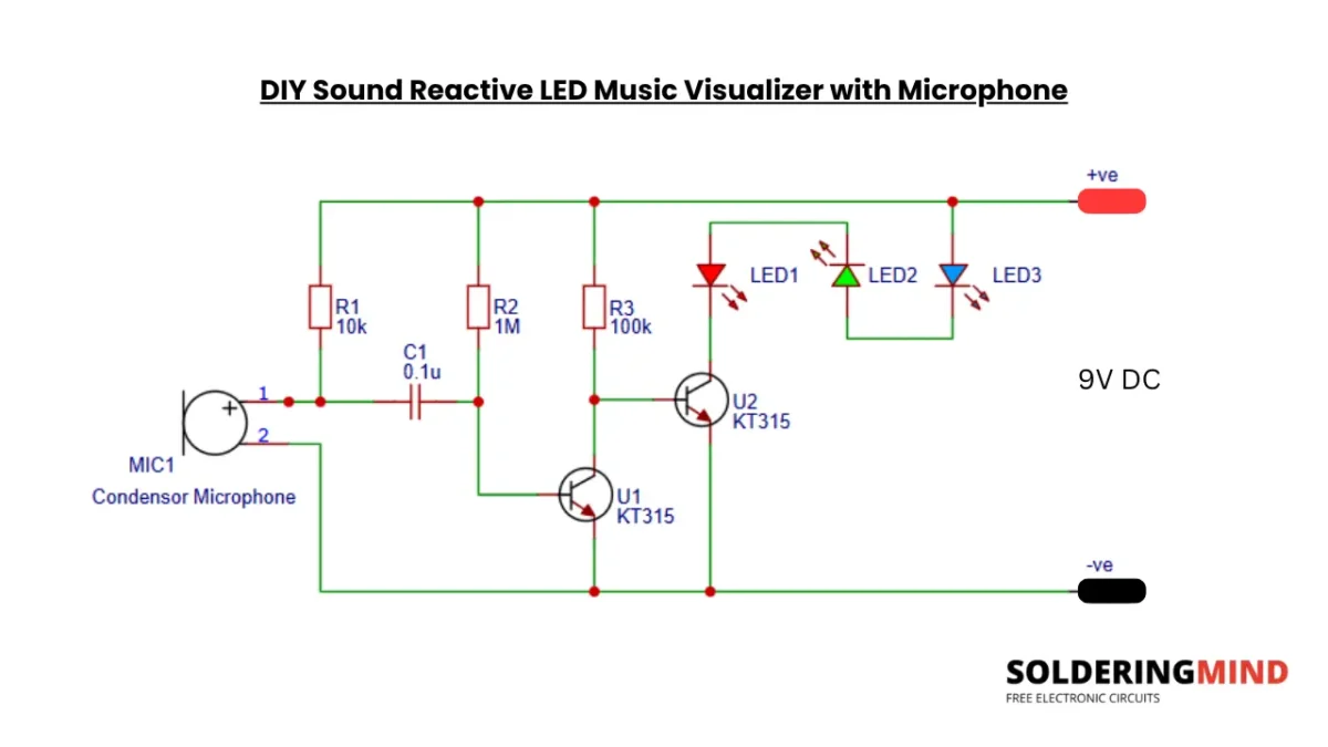
Use multi colored LED for good visual effect. The input supply voltage is 9V DC, you can use battery or dedicated 9V power adapter to turn the circuit ON. Always check the polarity of power supply before turn ON the circuit.
Main Components Used
- Condenser microphone.
- Two BJT NPN transistors (such as KT315 or BC547).
- Three LEDs.
- Bias resistors.
- 0.1uf Disc Coupling capacitor.
- 9V battery or DC power supply.
How the Sound Reactive LED Circuit Works
The working of this circuit is simple and easy to understand. I’m explain brief about its working for easy understanding. U1 and U2 are two NPN transistors, which are KT315. These are the audio amplifier transistors to boost the small input audio signal to a high current. The small signal from the microphone is captured and amplifying the weak signal to a large current for LED controlling.
Role of the Condenser Microphone in the Circuit
The condenser MIC is the main audio or sound detecting device. Which is directly connected with transistor audio amplifier section. The sound is converter to small and weak electrical signal. This signal is used for further amplification and flashing the LED.
Why the Microphone Needs a Bias Resistor
The 10K resistor is the biasing resistor, which is used to power the condenser microphone. When the required voltage for the MIC is received through the Resistor and provides a small audio signal to the transistor base through the coupling capacitor.
Applications of the Circuit
This simple sound activated light circuit has many real-world applications, which are most common in children’s educational project, Music reactive decorations, Acoustic sound indicator, DIY party lighting, etc.