In this article I’m sharing simple electronic project of Wire break alarm circuit. This circuit works by if The connected wire is broke that time the alarm starts and also give LED indication for alerting. The circuit diagram and working explanation given for you.
Circuit Diagram
Components Required
| Sl. No | Component Name | Value / Specification | Quantity |
|---|---|---|---|
| 1 | Resistor R1 | 150 Ω | 1 |
| 2 | Resistor R2 | 33 kΩ | 1 |
| 3 | LED | Standard (Red/Any color) | 1 |
| 4 | Buzzer | 12V DC Buzzer | 1 |
| 5 | MOSFET (Q1) | IRFZ44 / IRFZ44N | 1 |
| 6 | Power Supply | 12V DC | 1 |
| 7 | Connecting Wire | As per required length | 1 |
| 8 | Terminal Connectors | 1-pin (J1, J2) | 2 |
Circuit Connections
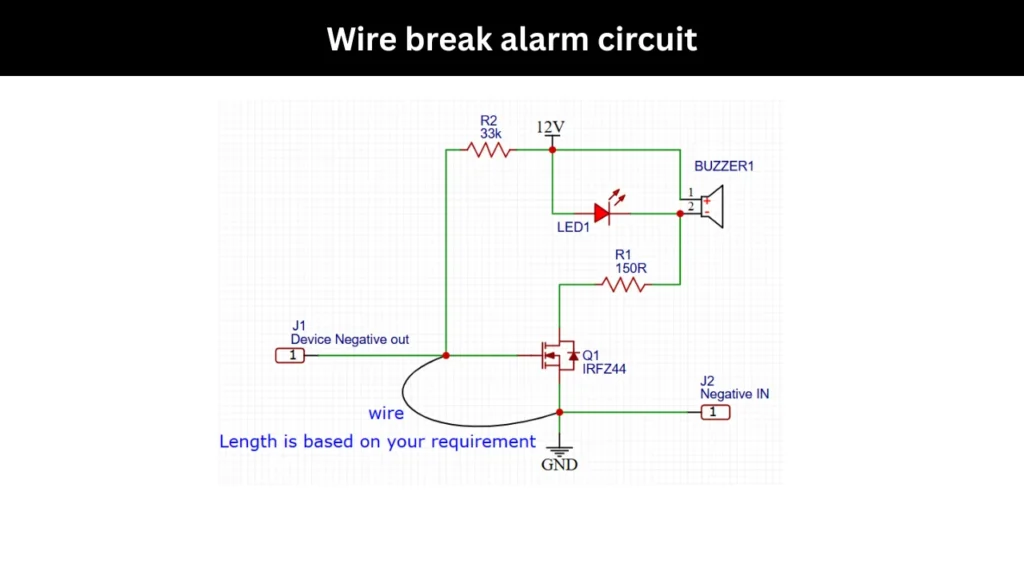
The wire break alarm circuit is working on a 12V DC supply. The positive voltage is directly connected to one terminal of the buzzer and also to one side of resistor R2 of 33kΩ. The other end of resistor R2 goes to the sensing line. Which is connected to the “Device Negative Out” pin of marked as J1.
An LED is connected in parallel with the buzzer, with its anode leg connected to the 12V line and its cathode connected toward the control path. Resistor R1 of 150Ω is placed in series between the buzzer/LED junction. This resistor helping to limits the current passing through the LED. This will protect the circuit components.
The MOSFET of IRFZ44 is acts as a switching device. its source pin is connected to ground and its drain connected to the load (buzzer and LED). The gate of the MOSFET is linked to the sensing wire loop, which runs between the “Device Negative Out” and “Negative IN”.
This wire loop can be extended to any required length and it acts as the external connection to be monitored. All the negative returns are tied together through J2 and connected to the ground line, This will completing the circuit connections.
Voltage Tester/Non-Contact Voltage Tester with Signal, Dual Range AC 12V/70V-1000V
- Brand: KAIWEETS
- Power Source: Corded Electric
- Color: Black
As an Amazon Associate, I earn from qualifying purchases.
🔥 Check Price on AmazonWorking Principle
The alarm circuit keeps checking whether the external wire loop is connected proper or not. When the wire is properly connected, the MOSFET gate stays at a low voltage level. This will keeps the MOSFET in turned OFF state. Because of this, no current is flows through the buzzer or the LED.
So both components remain off condition. The resistor R2 helps to maintain a stable condition and prevent the MOSFET gate does not accidentally turn on due to noise or small voltage changes.
If the wire gets cut or disconnected, the situation changes immediately. The gate of the MOSFET is then gets high positive voltage through resistor R2 from the 12V supply. Which will turns the MOSFET ON.
Once it turns on, the current will starts to flow through the buzzer and LED. This will make the buzzer to generate sound and the LED to glow. This gives a clear alert that the wire has been broken or cuts.