In this article I’m sharing a simple and very efficient Flasher circuit for your car or bike lights. You can connect 12V 60 watt lights to without any issues. This circuit is perfect for indicator dimming or flashing. The circuit diagram and connections are explained.
Circuit Diagram
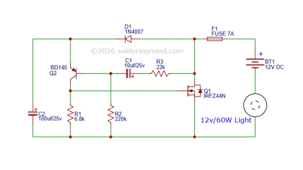
This flasher have few number of electronic components needed to work. The main component is the IRFZ44 MOSFET and BD140 transistor. The mosfet turn ON and OFF continuously makes the connected light turns ON and OFF.
Components Required
| Ref | Component Type | Value / Part Number |
|---|---|---|
| Q1 | N-channel MOSFET | IRFZ44N |
| Q2 | PNP Transistor | BD140 |
| D1 | Diode | 1N4007 |
| F1 | Fuse | 7A |
| R1 | Resistor | 6.8 kΩ |
| R2 | Resistor | 220 kΩ |
| R3 | Resistor | 22 kΩ |
| C1 | Electrolytic Capacitor | 10 µF / 25V |
| C2 | Electrolytic Capacitor | 100 µF / 25V |
| BT1 | Power Supply | 12V DC |
| Load | Light Bulb | 12V / 60W |
Universal for Bike Hazard Flasher/Blinker Waterproof 25 Patterns Flasher
- Fitment: Universal Fit Box Contain – 1 Flasher with Pattern Changer Switch
- Reliable performance
- All Indicators Can Operate in 16 Different Modes
As an Amazon Associate, I earn from qualifying purchases.
Circuit Connection
The connection is simple and easily assemble it on a breadboard if you want to test its working. I tested this circuit and working fine without any issues. 12V 60watt light is directly connect one end to battery negative polarity.
12V battery positive is connected through a 7A fuse and it goes to the MOSFET source pin and BD140 transistor emitter pin through a forward biased 1N4007 diode. This diode protect the circuit from reverse polarity.
The transistors collector pin is connected to the gate pin of IRFZ44 mosfet. The base pin of transistor is connected to the positive supply through a 10uf/25v electrolytic capacitor and 22K resistor.
Working Principle
This circuit is basically a delayed switch / soft start controller for a 12V load using a MOSFET. When power is applied, the capacitor C1 (10µF) begins charging slowly through R3 of value 22kΩ. which delays the voltage reaching the gate pin of the MOSFET IRFZ44N.
During this time, the transistor BD140 is helps to control the gate voltage, This will keeping the MOSFET initially off. As the capacitor C1 charges, the gate voltage gradually rises, this will turning the BD140 transistor on slowly instead of instantly. This results increase of current through the light, which will preventing sudden surge of currents.
Once capacitor C1 is fully charged it allows voltage to fully turn on the MOSFET, so the 12V/60W lamp glow at its full brightness. The resistor network of R1 and R2 stabilizes the biasing and ensures proper switching behavior. while C2 of 100µF capacitor is filters the supply for stable operation.