Build a simple LED chaser circuit using CD4017 and NE555 timer ic. The circuit contains a small number of components and very beginners can also do the project. You can also check the updated project of CD4017 here. The LED Chaser works with the help of a 6v-9v DC supply. so keep in mind that do not exceed the input voltage rate above its maximum input voltage range.
CD4017 and also NE555 timers ic working perfectly in 6v DC voltage, so using a voltage regulator of LM7806 is better to control the input voltage fluctuations. I hope you got some basic ideas about this LED chaser circuit, ok let’s discuss the further details of the circuit.
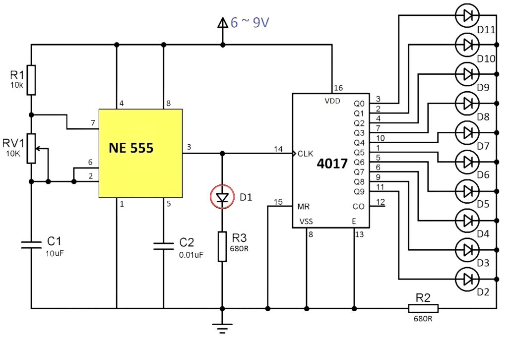
LED Chaser Circuit Diagram
Components List
- CD4017 IC – 1
- NE555 Timer ic – 1
- LED – 11
- 10 K preset pot – 1
- 10uf capacitor – 1
- 0.01uf capacitor – 1
- 10 K resistor – 1
- 680 OHM resistor – 1
- 9v battery – 1
- battery connector
LED Chaser Working
The 555 timer is wired as an astable multivibrator & its output is directly connected to the clock input of counter ic CD4017. The output pulse frequency of the 555 timer is controlled by R1, RV1, and also the capacitor C1. The positive voltage is provided to the 8th pin and negative to the 1st Pin of 555 IC. The control voltage of the 5th pin is not used to connect. To avoid the frequency noise capacitor C2 0.01uf to the ground pin.
The LED D1 is connected to the clock pin of CD4017 IC. it is used to indicate the output of 555 IC and the resistor 680 ohms is for limiting the current passage through the LED.
Similarly, the 16th pin of CD4017 is connected to the positive supply voltage, and 8 the pin to the negative. The clock enables pin 13 to connect to the ground and is an active low input. The clock pin of the 14th is connected to the output pin of 555 ic.
Only a single resistor is required to control the whole LED since only one LED will turn on and off at a time.
The output frequency of 555 timer IC can be calculated using this equation.
Output Frequency = 1.44/((R1 + 2RV1) * C1)

Great job
Thanks buddy