Here is the simple tutorial and complete project details about how to control two motors with a dual-axial Joystick. Let’s check the complete circuit diagram and project details given below.
Introduction
The joystick motor controller works by taking an input from a joystick and converting that input into control signals. Then that is sent to a motor driver or motor controller.The motor controller then uses these signals to control the speed and direction of the motor.
The joystick typically provides two-axis control, with one axis controlling the forward/backward movement and the other controlling the left/right movement.The movement of the joystick is usually converted into a voltage signal that is proportional to the position of the joystick.
The voltage signal from the joystick is then processed by a control circuitry to generate the control signals for the motor controller.The control signals are usually in the form of pulse width modulation (PWM) signals, which are a series of pulses that control the duty cycle of the motor.
The duty cycle determines the speed of the motor, with a higher duty cycle resulting in a faster motor speed. The direction of the motor is controlled by reversing the polarity of the voltage signal sent to the motor controller.The motor controller then takes the PWM signals and uses them to drive the motor, controlling its speed and direction.
Also Check: Arduino related Projects
Some motor controllers may also include additional features such as overcurrent protection, which can prevent damage to the motor in case of a fault.
Overall, a joystick motor controller provides a simple and intuitive way to control the movement of a motor, making it an ideal choice for applications such as robotics, remote-controlled vehicles, and other types of automation.The simple and easy two-motor controller circuit diagram and components lists given below.
Things Need to Start
- Electronic components
- Dotted PCB
- Soldering iron, Lead, and paste.
- Cutting player, Screwdriver.
- Multi meter
Circuit Diagram
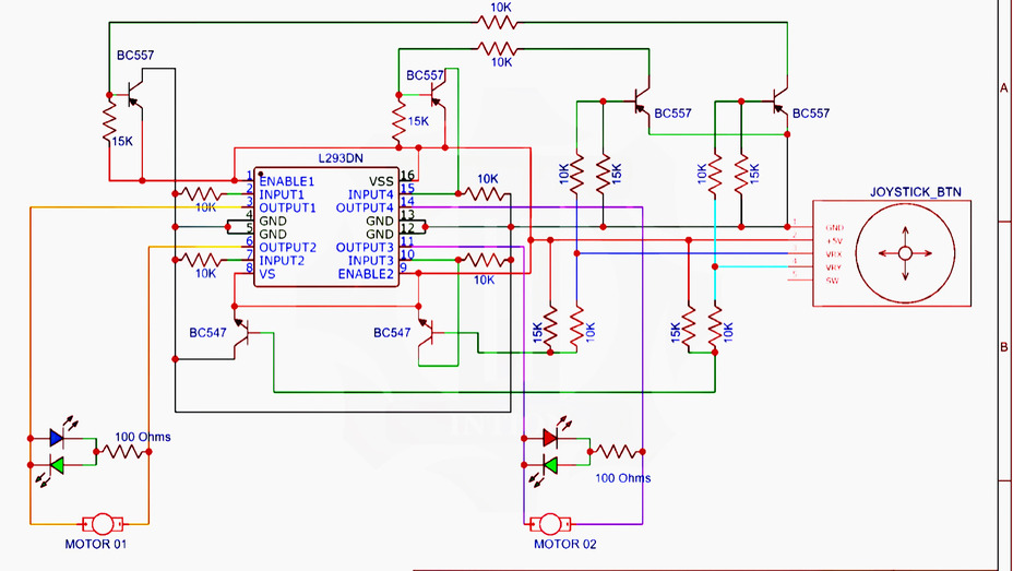
The L293DN ic is a dual H-bridge motor driver IC (integrated circuit) designed to control the speed and direction of DC motors. This IC is widely used in robotics and other applications that require precise control of motor speed and direction.
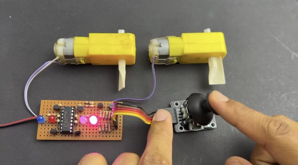
The circuit can able to control the two motors. It can move forward, backward, and in either direction as per the movement of the joystick.
Note: The 8 and 16th pin of the IC connected to positive and Gnd pins connected to ground to power this circuit. Provide maximum voltage of 5v DC.
Components Required
- Dual axial Joystick
- L23D Motor driver IC
- Two toy car Motor
- BC557 transistor – 4
- BC547 transistor -2
- 15k resistor -6
- 10K resistor – 8
- 100 ohms resistor -2
- LED – 4
Joystick Module
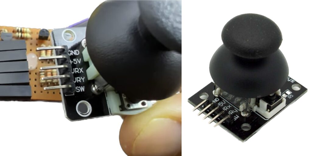
Pinout
| Pin Number | Pin Name | Description |
|---|---|---|
| 1 | GND | Ground |
| 2 | VCC | Power supply voltage (typically +5V) |
| 3 | VRx | Analog output for X-axis movement |
| 4 | VRy | Analog output for Y-axis movement |
| 5 | SW | Digital output for joystick button (optional) |
L23d Motor Driver IC
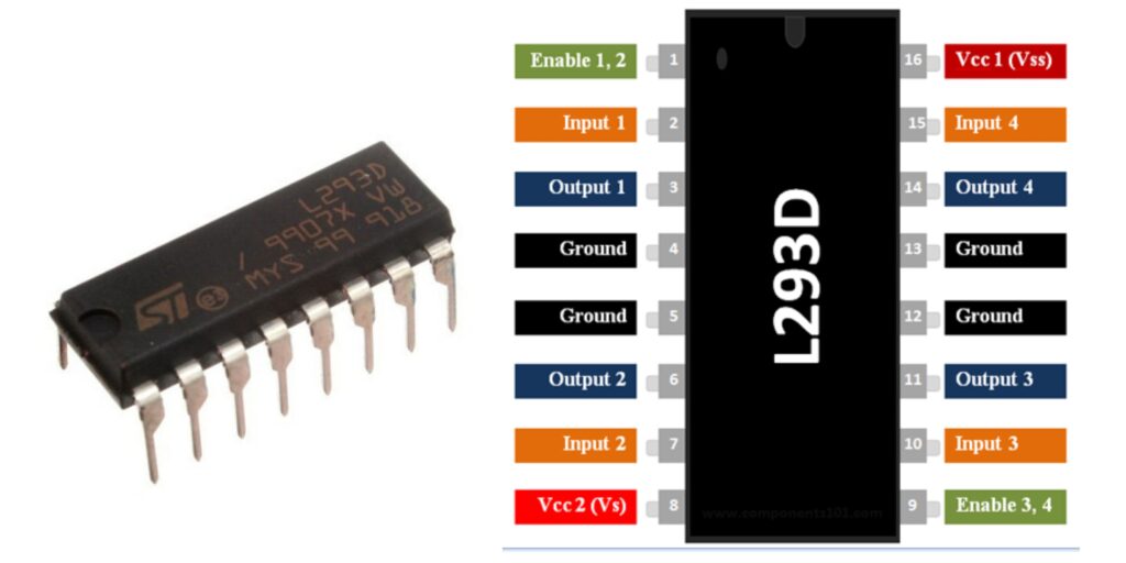
L293d is a dual H-bridge motor driver IC, capable of driving 2 DC motors in both directions with a maximum current of 1A per motor.
The L293d is commonly used in robotics, automation, and other projects that require precise motor control. It is available in a variety of packages, including the 16-pin DIP and the 20-pin SOIC. It consists of two H-bridges, each with four inputs (two for direction and two for PWM speed control) and four outputs (two for each motor terminal).