Hello, welcome back with another interesting Arduino Uno project is here. The Arduino Clock, You can easily build an Arduino clock using a few components. The brain of this project is ATMEGA 328P programming IC. So we are going to program this IC and use it as a fantastic Arduino Digital clock.
Arduino Clock Circuit Diagram

Components Required
- Arduino Uno or Programmed ATMEGA 328 IC
- 16 Mhz crystal
- 22pf ceramic capacitor
- Push button
- 7805 Regulator IC
- LED
- Common Anode 7-Segment Display
- 10K, 330 R resistors
- 9v or 12v Battery
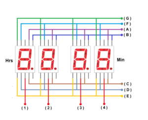
4 Bit Seven Segment Connection for Arduino Clock
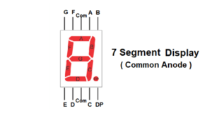
First, you need to build a 4-bit seven-segment display by connecting all pins as per the circuit diagram given in the schematics given in below. The seven-segment display is a common anode type. So if you are buying this display please confirm it first. Pin A, B, C, D E, F, and G are represented in the image for connection. The numbering from 1 to 4 is powering the 7-segment display. Those pins are going to the Arduino uno or ATMEGA328P IC pins. Buy 7 segment common anode display
The Arduino clock works with 12Hrs setup mode. There are two push switches available in the circuit diagram. The push switch is acts as the control of adjusting the time on the display. By pressing these switches you can easily change the numbers on the display. Buy ATMEGA328P with pre Bootloader Installed
A 9v battery is connected with the circuit diagram, You can replace this battery with a 12v battery without any issues. The 7805 regulator IC provides only 5V to the microcontroller and also the seven-segment display, so there are no worries about overvoltage or any voltage fluctuation in the external power source.
Arduino Clock Programming Code
//*** Solderingmind.com ***

#include "SevSeg.h"
 SevSeg Display;
 const unsigned long period = 1000;
 const unsigned long led_period = 500;
 unsigned long startMillis;
 unsigned long led_startMillis;
 unsigned long currentMillis;
 unsigned long led_currentMillis;

 const int hrs_btn = A5;
 const int min_btn = A4;
 const int ledPin = 13;

 int Hrs = 12;
 int Min = 0;
 int Sec = 0;
 int Time;
 int ledState = LOW;
 void setup()
 {
 pinMode(hrs_btn, INPUT_PULLUP);
 pinMode(min_btn, INPUT_PULLUP);
 pinMode(ledPin, OUTPUT);
 byte numDigits = 4;

 byte digitPins[] = {A3,A2,A1,A0};
 byte segmentPins[] = {2,3,4,5,6,7,8};

 bool resistorsOnSegments = true;
 bool updateWithDelaysIn = true;

 byte hardwareConfig = COMMON_ANODE;

 Display.begin(hardwareConfig, numDigits, digitPins, segmentPins, resistorsOnSegments);
 Display.setBrightness(100);
 }
 void loop()
 {
 currentMillis = millis();
 if (currentMillis - startMillis >= period)
 {
 Sec = Sec + 1;
 startMillis = currentMillis;
 }
 led_currentMillis = millis();
 if (led_currentMillis - led_startMillis >= led_period)
 {
 led_startMillis = led_currentMillis;
 if (ledState == LOW)
 {
 ledState = HIGH;
 if (digitalRead(hrs_btn) == LOW)
 {
 Hrs = Hrs + 1;
 }
 if (digitalRead(min_btn) == LOW)
 {
 Min = Min + 1;
 Sec = 0;
 }
 }
 else
 {
 ledState = LOW;
 }
 digitalWrite(ledPin, ledState);
 }
 if (Sec == 60)
 {
 Sec = 0;
 Min = Min + 1;
 }
 if (Min == 60)
 {
 Min = 0;
 Hrs = Hrs + 1;
 }
 if (Hrs == 13)
 {
 Hrs = 1;
 }
 Time = Hrs * 100 + Min;
 Display.setNumber(Time);
 Display.refreshDisplay();
} 

Thanks for finally talking about > How to Make Arduino Clkck usding 7-Segmjent Display Klara
Hi this is greate and working with low side 4X NPN transistors.. Can you add DS18D20 Temp Sensor to it …..?