Detects any ac voltage using this voltage detector circuit. The schematic and the working of this circuit is discussed here.
Introduction
The CD4017 is like a helpful electronic component that can be used in different circuits. We can use it to create a basic circuit that tells us if there’s electricity in an AC power source. Let’s make a simple design using the CD4017 for this purpose.
Circuit diagram

Working
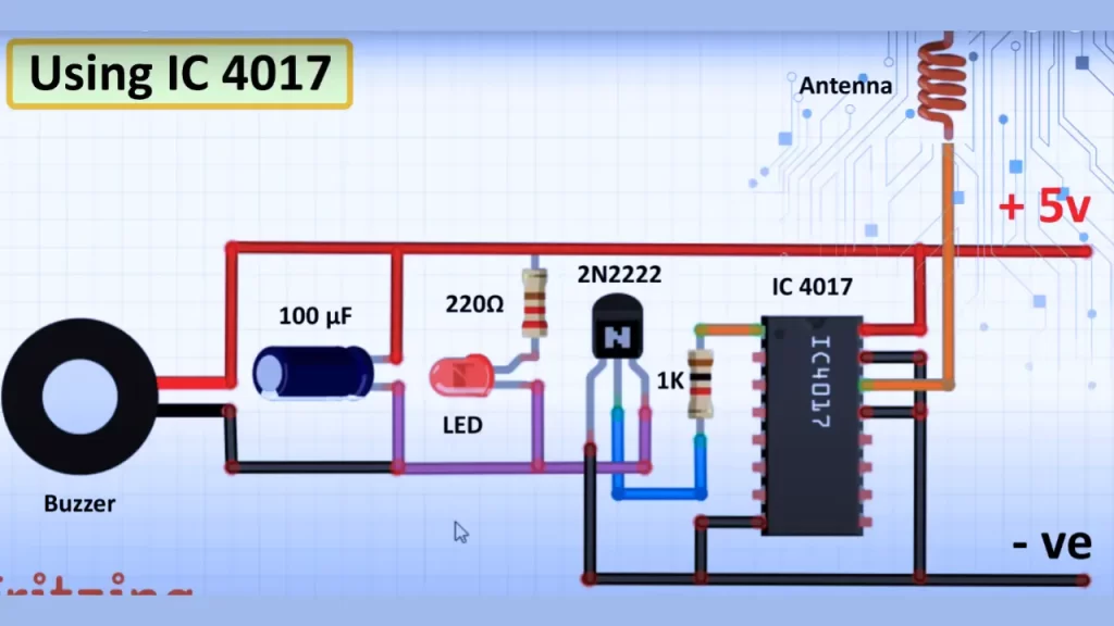
In this circuit, the CD4017 serves as the main IC for detecting AC voltage and triggering the buzzer sound and LED light. A small copper wire is employed as the antenna.
The 5V DC supply is sufficient for the operation of this AC detection circuit. When the antenna detects any electromagnetic field (EMF) produced by electricity, it transmits the signal to the CD4017 IC.
Subsequently, the IC activates the 2N2222 NPN transistor, leading to the illumination of the LED and the emission of a buzzer sound. The schematic is highly sensitive, and by holding the antenna with your hand, the circuit initiates its functioning.
| Also Check: Other DIY Projects


