Class H Amplifiers are energy efficient audio amplifiers and has high power handling capacity. The Class H is commonly used in High power audio systems. The Circuit of this amplifier is entirely different from the Class A, Class B or any other type of audio amplifiers. In class H amplifiers the power supply is adjusted dynamically to match the input signal needs. This will reduce the power consumption and heat generation.
What is the difference between Class G and Class H amps?
From internet More articles are explaining class H with Class G audio amps. But both are different, The original class H amplifier is designed with a large capacitor and uses it in the circuit when it is needed. And the other one is external modulated power supply for switching, this helps to switch the supply voltage to higher voltage when it is needed.
Class H Amplifier Circuit
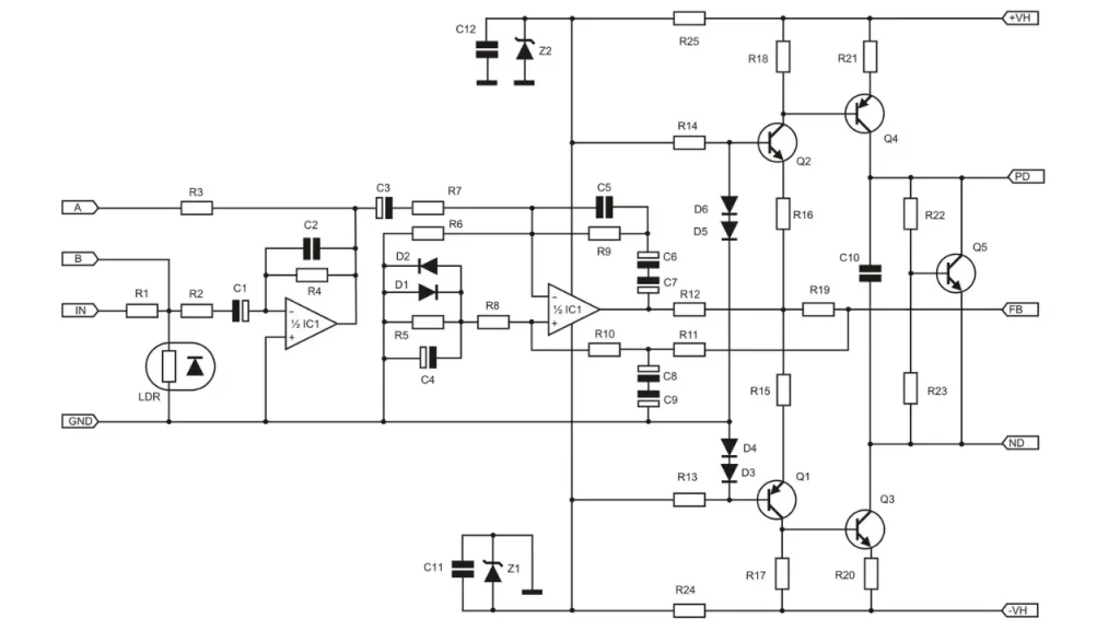
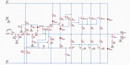
This given circuit gives 900watt RMS output at the mentioned input DC voltage. This circuit is only the driver stage, the out put stage is given below. The components list of driver stage is also given below.
Components Required for Driver stage
Below is the part list for the H900 VAS (Voltage Amplification Stage):
Resistors
- R1: 3.3k ohm
- R2: 10k ohm
- R3: 33k ohm
- R4: 43k ohm
- R5: 47k ohm
- R6, R7, R8, R9, R13, R14: 4.7k ohm
- R10, R11, R19: 22k ohm
- R12, R15, R16: 1k ohm
- R17, R18: 1.5k ohm
- R20, R21: 100 ohm
- R22: 680 ohm
- R23: 330 ohm
- R24, R25: 2.2k ohm (2W)
Capacitors
- C1, C8, C9: 22uF (25V)
- C2: 33pF
- C3, C4: 2.2uF (63V)
- C5: 470pF
- C6, C7: 47uF (25V)
- C10, C11, C12: 100nF (63V)
Diodes
- D1, D2, D3, D4, D5, D6: 1N4148
Zener Diodes
- Z1, Z2: ZY15V
Transistors
Integrated Circuit
- IC1: NE5532
Light Dependent Resistor
- LDR: NSL32
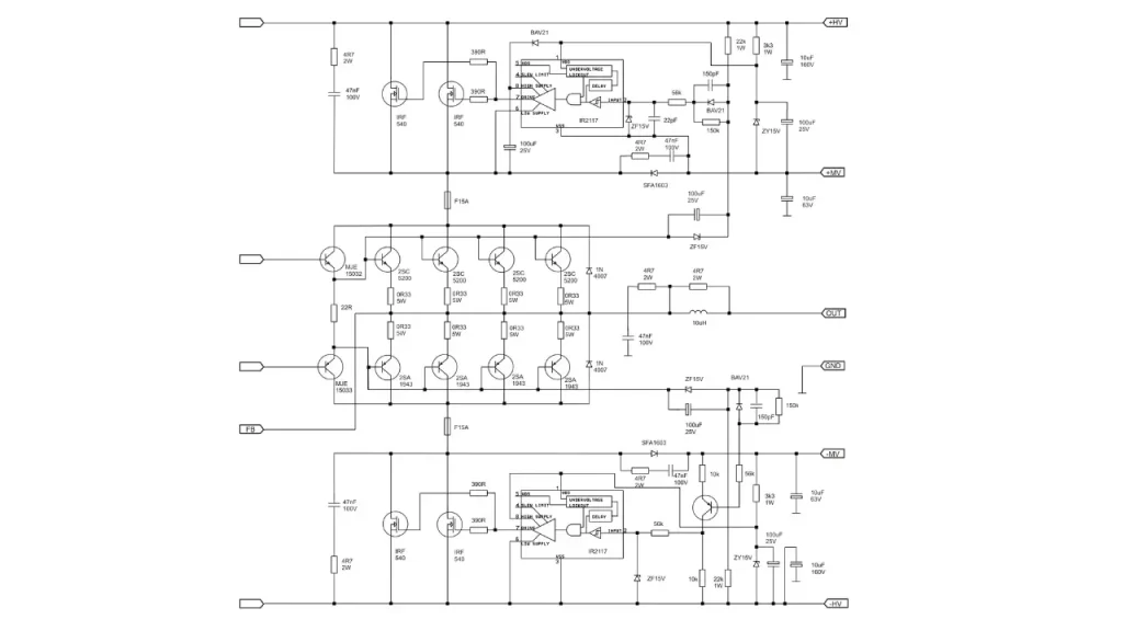
Class H 900 watt Output Stage Circuit

Is it apex h900?? Do you have pcb for this amp?