Lets build a Low pass filter circuit using NE5532 op camp IC. The subwoofer amplifier needs a filter board to drive the low frequency output. This circuit is specially designed to restrict the high frequency and allowing the low-frequency signals to the subwoofer amplifier board.
Circuit Diagram
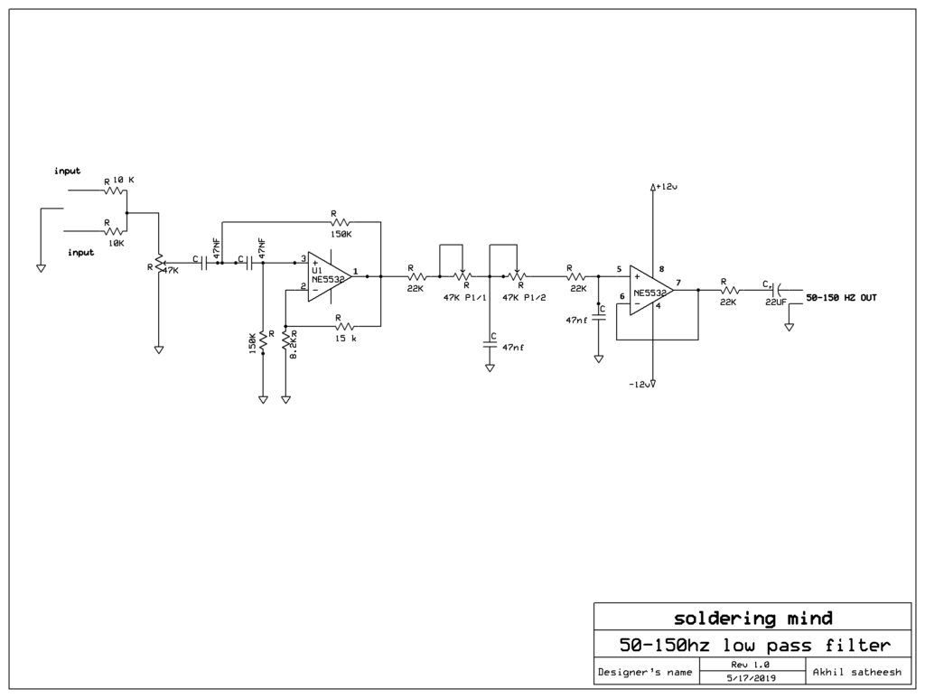
The subwoofer working frequency is in between 50 hertz to 150 hertz. To get low frequency, it’s specially designing a low pass filter circuits as per the diagram. Here are going to discuss the low pass filter-making using NE5532 IC. This NE5532 IC is an op amp IC. Two number of operational amplifier is inbuilt in it.
Features of NE5532 IC
This IC provided the best audio output and less noise, this IC is a high-speed audio operational amplifier. The circuit is very simple to set up and has a symmetrical power supply, that means a dual power supply. The transformer must be used 9 to 12 volt 500 milliamperes with a center tap. In many cases the power supply, we are taking from the power amplifier that’s also good.
The low pass filters are mainly used in the subwoofer amplifier because the subwoofer amplifier needs that. The subwoofer is used for reproducing the low-frequency audios to high power output.
Check it if you want to know more about Subwoofer amplifier

4558 low pass filter pcb layout pls
4558 low pass filter pcb layout
Upload soon