The Astable multivibrator circuit calculator is designed to get values of Time high, Time low, Frequency and duty cycle. The circuit producing a continuous oscillating frequency from 555 Timer IC. So in this circuit configuration the 555 timer continuously switches the output signal between high and low states. This producing frequency is in a square wave output. It’s called “astable” because it does not have a stable state the output keeps oscillating between high and low states. This output frequency and other values are controlled by the connected resistors R1, R2 and capacitor C1.
555 Astable Multivibrator Calculator
Enter the Values as Per Your Requirements
How to Use 555 Astable Multivibrator Calculator
The Astable Multivibrator Calculator is a useful tool to easily calculate the frequency, time period, time high, time low, and duty cycle of a 555 timer circuit. This calculator is specific for astable mode of circuit configuration. To use the calculator you need to enter the values of the two resistors R1 and R2 and the capacitance (C) in their respective fields.
Then you need to select the units for each component, for resistor it will show Ohms (Ω), Kilo-ohms (KΩ), Mega-ohms (MΩ). For the capacitor units of Farads (F), Microfarads (µF) and Nanofarads (nF). After selection click the “Calculate” button to get the necessary calculations.
Once the calculation is complete, the results will be displayed which including the frequency of oscillation, time for the output to remain high (time high), time for the output to remain low (time low), the total time period of the cycle and the duty cycle.
Formula
Frequency Calculation
The equation for calculating the frequency of an astable multivibrator configuration is
f = 1.44 / (R1 + 2R2)C
- C is the capacitor value in farads.
- R1 and R2 are the resistor values in ohms
High Time Equation (Thigh)
Thigh = 0.693 (R1+R2) C
Low Time Equation (Tlow)
Tlow = 0.693 x R2 x C
Duty Cycle
D = Thigh / (Thigh+ Tlow) x 100
What is 555 Timer Astable Multivibrator
Astable Multivibrator is an electronic circuit, that used to implement flip flops, timers, and oscillators. The designing and working of 555 based Astable Multivibrator is done by using some external components like capacitor and resistors. Any changes is happened on the connected RC Tank will change the output frequency, Time period and Duty cycle.
555 Timer IC is very cheap and easy to assemble, so we can easily build an Astable Multivibrator circuit. Any changes in the values of R1, R2 and C1 will changes the output signal also. You can use the above 555 timer calculator tools to find the output frequency of your Astable Multivibrator circuit.
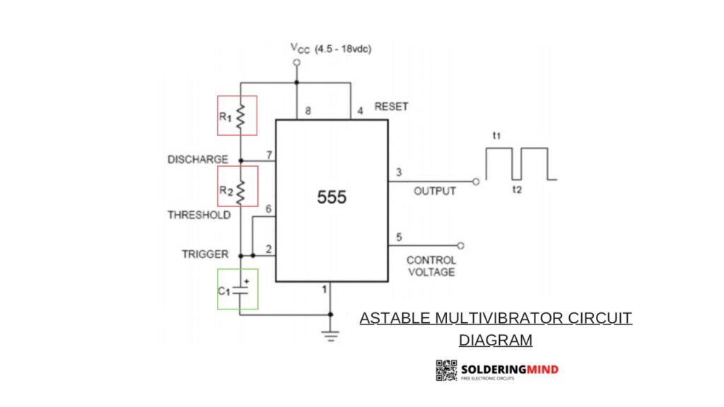
Working Principle
The 555 timer IC based multivibrator circuit consist of resistors, capacitors to build astable multivibrator or a timed pulse circuit of monostable multivibrator. In its astable mode, it continuously switches the signal between high and low states, this will creates a square wave output. This is achieved by charging and discharging of capacitor through the resistors.
This capacitor and resistors controlling the timing of the output. The 555 timer compares voltage levels across the capacitor with built in internal reference voltages using two voltage comparators. When the capacitor’s voltage reaches a specific threshold level the output state changes and the cycle repeats continuously. In monostable mode circuit it produces a single pulse when any signal is triggered. Here the pulse width determined by the external resistor and capacitors.
Calculations Example
Let’s assume you have the following components:
- R1=4.7 kΩ
- R2=10 kΩ
- C1=100 nF
Calculating the Frequency
First you need to convert all the given values to its standard units:
- 4.7 kΩ=4.7×10³ Ω
- 10 kΩ=10×103 Ω
- 100 nF=100×10−9 F
f = 1.44 / (R1 + 2R2)C
f = 1.44 / (4.7×10³ + 2 x 10 x 103) 100 x 10-9
f = 1.44 / (4.7×10³ + 20 x 103) 100 x 10-9
= 1.44 / 24×103 x 100 x 10-9
f = 582.59Hz approximately.
Calculating Duty Cycle
Lets calculates the frequency and Duty cycle of the circuit. D = Thigh / (Thigh+ Tlow) x 100
so, Thigh = 0.693 (R1+R2) C
Thigh = 0.693 (4.7 x 10³+ 10 x 103) 100 x 10-9
Thigh = 1.019ms
Tlow = 0.693 x R2 x C
= 0.693 x 10x 103 x 100x 10-9
Tlow = 0.693ms
Duty cycle (D) = 1.019ms / (1.019ms + 0.693ms) x100
D = 1.019 / 1.712 x 100
Duty cycle = 59.5 % approximately.
Uses of Astable Multivibrator
- Generating PWM signals – The 555 astable multivibrator circuit generating PWM signal so it is used to control the speed of motors, dim LEDs, or adjust the brightness of displays. The duty cycle of the PWM signal is controlled by the values of capacitor and resistors.
- Tone Generator – The astable multivibrator producing high and low signal in output which is used as generate audio tones for alarms, sound effects, or simple musical devices like electronic buzzers.
- Flashing LEDs – This circuits also using for turn LED on or OFF based on the frequency. so it is useful in in various signaling and visual effects, such as in LED flashers, blinkers, or strobe lights.
- Frequency Generator – in the given circuit of astable multivibrator replacing the resistors with a potentiometer to adjust the output frequency and duty cycle of the circuit. so it is used for testing audio equipment’s and generating variable frequency for testing.
FAQ
No, a true 50% duty cycle is not achievable in the standard configuration. To achieve a 50% duty cycle, you would need a modified configuration, such as a 555 timer in a CMOS configuration or a different timing circuit.
Yes, you can use the 555 timer in astable mode to generate PWM signals, but the duty cycle may not be exactly 50%. By adjusting the resistor values, you can modify the duty cycle to suit your needs for PWM applications.
In a 555 timer astable multivibrator configuration, the duty cycle refers to the percentage of time the output remains high in each cycle of the square wave produced. It is determined by the values of the resistors R1 and R2 and the capacitor C.