Design custom RF attenuators in seconds! Compute R1, R2, and R3 resistor values for equal and unequal impedance Pi configurations with a live, interactive schematic diagram.
The pi attenuator circuit consists of a series resistor and both ends are connected with a shunt resistor. The other end of the shunt resistor is connected to ground or the negative supply. This circuit configuration helps to attenuate the input/output signal. This calculator is used to find the value of R1 and R2 in an equal impedance circuit, and the values of R1, R2, and R3 in an unbalanced impedance configuration.
How to Use Pi Attenuator Calculator
There are two types of pi attenuator configurations in a circuit based on the source and load impedance. First, you need to select the type of circuit you want to calculate. If you are selecting unequal impedance, you need to enter the values in the fields "Attenuation (dB)" and "Impedance (Z0)" to calculate the values of R1 and R2. This will be calculated automatically.
If you select the unequal impedance option, you will see additional fields for Source impedance, Load impedance, and the R3 value. So you need to enter the Attenuation, Source impedance, and Load impedance to calculate the resistance values of R1, R2, and R3. All resistance values will be displayed in the standard unit of ohms.
You can clear the entry fields using the "Reset" button. Press the reset button to start entering new values to calculate.
Types of PI Attenuator
- Pi attenuator with equal impedance.
- Pi attenuator with unequal impedance.
Pi Attenuator with Equal Impedances
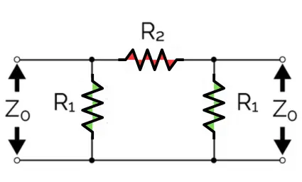
In equal impedance attenuator circuit configuration, the source impedance value (Z0) is equal to the load impedance value (ZL), so this is called an equal impedance configuration. Therefore, the R1 value of the shunt resistor is the same.
First, convert the desired attenuation from decibels (dB) to a linear voltage ratio (K):
R1 and R2 is equal then the equation will be,
Pi Attenuator with Unequal Impedances
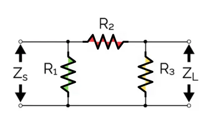
The attenuator with equal unequal impedance means the input impedance and Load impedance are different. In this situation we need different formula to calculates the both shunt resistors values. In unequal impedance attenuator input impedance is denoted as "Zs" and Load impedance is represented as "Zl". The shunt resistor in input impedance is R1 and R3 is in the Load impedance. To calculates the R1, R2 and R3 using the formula of,
Example Using Standard 50 ohms Impedance (Z0 = 50 ohms) System
| Attenuation (dB) | K Ratio | R1 (R3) Value | R2 Value |
|---|---|---|---|
| 3 dB | 1.413 | 292.4 Ω | 17.6 Ω |
| 6 dB | 1.995 | 150.5 Ω | 37.3 Ω |
| 10 dB | 3.162 | 96.2 Ω | 71.2 Ω |
| 20 dB | 10.000 | 61.1 Ω | 247.5 Ω |