This voltage divider calculator will help you find the output voltage of the resistor divider circuit. Enter the values of the source voltage and resistor values of Ra and Rb to calculate. You must remember that the output voltage (Vout) of the divider circuit will be less than or equal to the input source voltage (Vin).
How to use Voltage Divider Calculator
You can easily determine the output voltage of a voltage divider circuit using this simple calculator tool. First, enter the source voltage in the designated field and the values for Resistance A and Resistance B in their respective fields. You can choose the units using the drop-down menus next to each resistance input. After entering the values, automatically calculate the output voltage. You can also clear the inputs by clicking the “Reset” button. Make sure all the values are positive and valid for accurate results.
Voltage Divider Formula
- Vout = Output voltage (the voltage dropped across RB).
- Vin = Source input voltage .
- RA = Top resistor (connected to Vin).
- RB = Bottom resistor (connected to Ground).
Voltage Divider Circuit Diagram
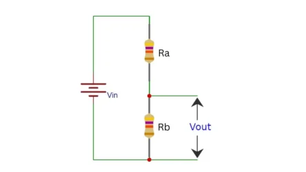
The voltage divider is a two-resistor combination circuit. The two resistors are connected in series and the voltage is taken out from the common shorted end of both resistors. The voltage divider turns a large voltage into a smaller one. If you want to measure the output voltage of a voltage divider, use the voltage divider calculator tool above.
Use cases
- Reading analog sensors (e.g., LDR, thermistors)
- Level shifting for microcontrollers (5V to 3.3V)
- Reducing voltage for ADC inputs
- Biasing transistors.
Applications of Voltage Divider
The voltage divider has many applications in electronics engineering and circuit development. A few number of applications are discussing here.
1. Variable resistors
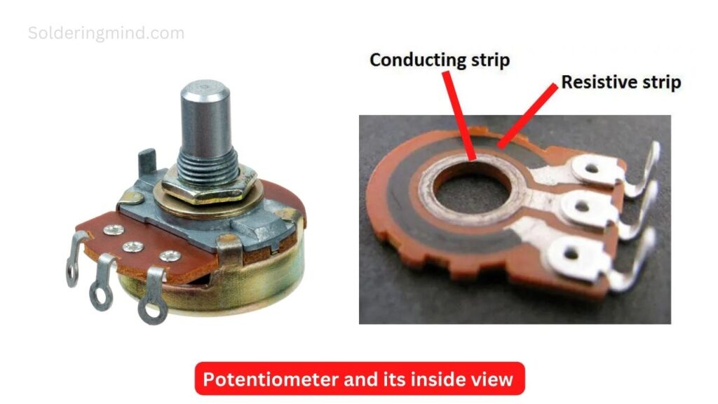
A variable resistor is used to adjust the potential difference in a circuit. Variable resistors are also known as potentiometers. A potentiometer has three terminals; the two outer terminals connect to a common resistive track. The third terminal is a sliding contact that moves along the track to adjust the resistance value.
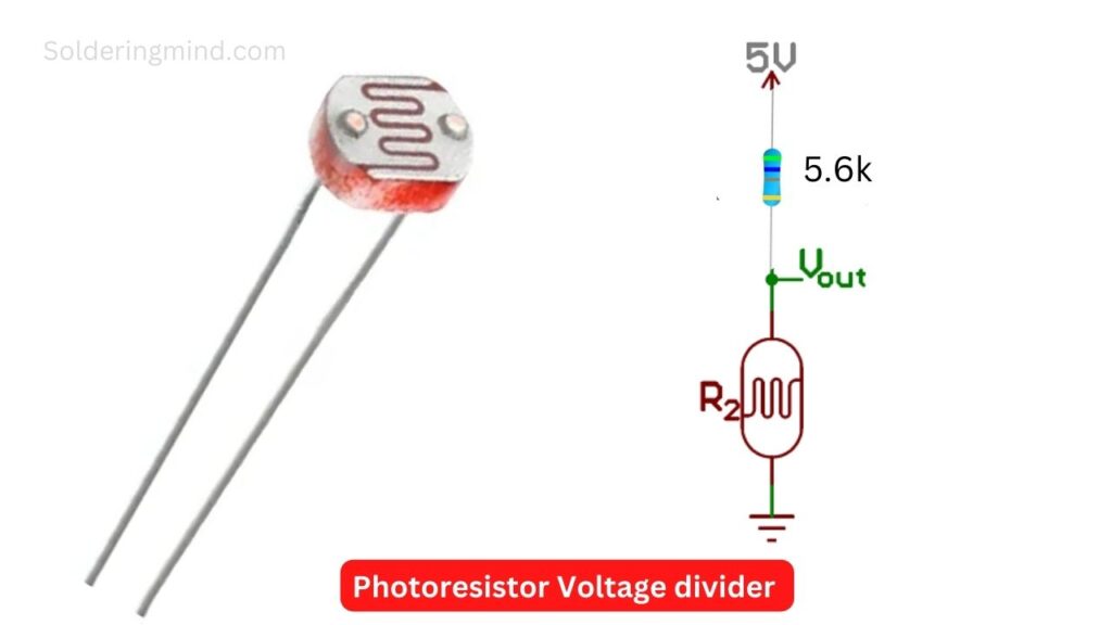
2. LDR ( Light dependent resistor ) Circuit
Also Check: Resistance vs impedance
Light-dependent resistors are also known as photoresistors. The internal resistance of the electronic component will change when any light falls on it. So this is a self-adjusting resistor; if you connect a resistor in series with an LDR, the common junction of the LDR and the resistor is taken out. This acts as a voltage divider in the circuit.
3. Rheostat
The rheostat also has many similarities to the potentiometer. But they are not using it as a voltage divider because it has two terminals. One end of the rheostat is connected to a wiper, which wipes over it. In older electronics, the rheostat is used as a controller to control high voltage, like bulb loads, motors, etc. The rheostat is constructed with copper wires wound on toroidal cores, and it creates resistance.
4. Voltmeter circuit
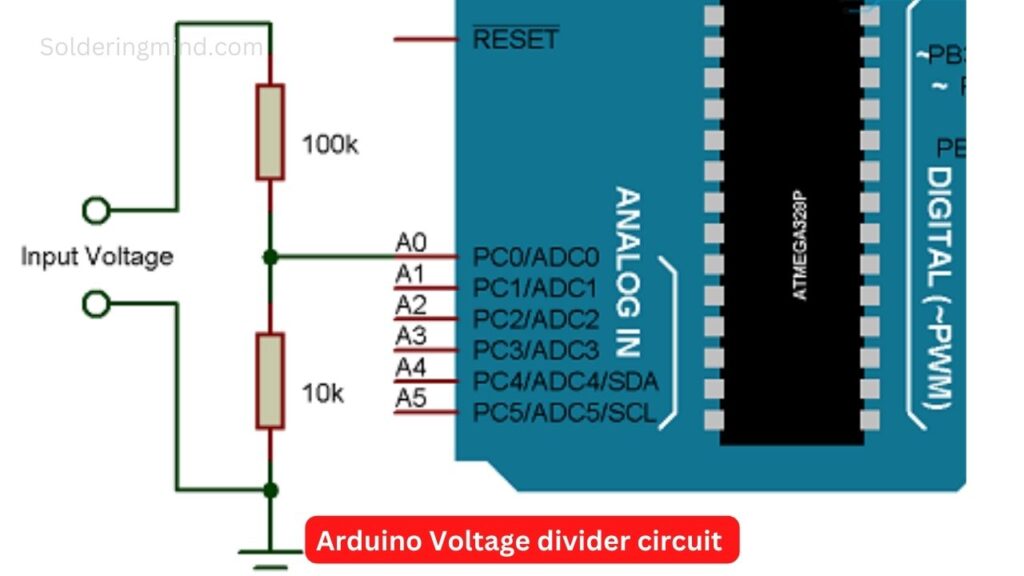
Most Arduino and inverter circuits have a voltage divider on them. The voltage divider provides a lower voltage than the input. This reduced voltage can be measured within the Arduino input range. The specific code is used for voltage dividers in Arduino projects.
Frequently Asked Questions (FAQ)
Yes you can calculates the current through the resistors of voltage divider using the formula of I = Vin / (Ra + Rb) where Ra is the positive side connected resistor and Rb is negative side connected resistor.
The voltage divider circuit will reduces the output voltage comparing to the input voltage, so this circuit is useful for sensors voltage scaling, reference voltage for Arduino and biasing the transistors.
Also Check: Parallel resistor calculator

thank you from Morocco
You are welcome