This article shares the simple Threshold Device Circuit for a Relay with Small Turn-On and Turn-Off Voltage Difference. The topic may be confusing to readers, so I’ll explain it briefly, which will help you understand this. The electromagnetic relay needs a specific voltage level to turn on and turn off. If the relay rated 12V will begin energizing at a voltage of 5.5V. At this lower voltage, the relay contact pressure is less, resulting in slow switching performance.
Normal 12V Relay and its Behavior in Voltage differences
When a full 12V charge is applied to the relay, the relay operates normally. The contacts get enough tight and no issue with slow performance. When the supply voltage is gradually decreased below 12V, the relay contact is not immediately released. It may remain in contact until the coil voltage falls to 2.5V. It is lower than its turn-on voltage.
The turn-on and turn off voltage will cause unwanted behavior in the circuit. In this situation, the relay works unpredictably if the voltage changes. This article shares the threshold device circuit that will minimize the relay on/off voltage differences. The circuit only gives voltage to the relay if the supply voltage reaches the normal value (11.6V) and de-energizes when the supply voltage drops about 0.2V (11.4V) from the normal value.
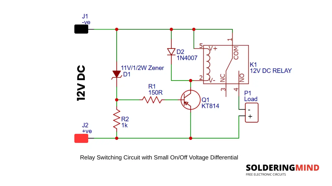
Relay Threshold Circuit Schematic with Close Turn-On and Turn-Off Voltages
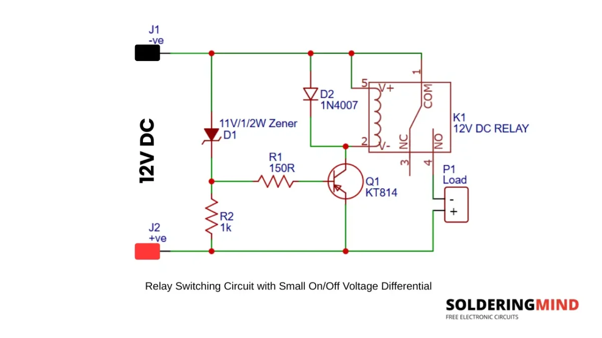
The circuit turns on relay in 11.8V and turn it off in 11.4 V. The input voltage is 12V DC. The difference in Relay ON and OFF is around 0.2V.
Components Required
- Q1 – KT814 PNP transistor
- K1 – 12 V DC electromagnetic relay (SPDT)
- D1 – 11 V, 0.5 W Zener diode
- D2 – 1N4007 rectifier diode (flyback protection)
- R1 – 150 Ω, ¼ W resistor
- R2 – 1 kΩ, ¼ W resistor
- J1 – 12 V DC input (Negative terminal)
- J2 – 12 V DC input (Positive terminal)
- P1 – Load connection terminal
- 12 V DC power supply
Also Check : BC547 Relay Circuit
Circuit Operation
The input stage of the circuit consist voltage reference circuit formed by a Zener diode and a 1K resistor. The Zener diode has a voltage breakdown of 11 V. When the input voltage increases, the Zener diode conducts only if the input voltage is above 11 V.
A higher negative voltage across the divider circuit will turn on the KT814 PNP transistor and conduct the relay and contacts to switch. When the supply voltage falls below 11.4 V, the transistor stops conducting and turns off the relay. This on and off will happens quick when the voltage fluctuates between 0.2 V difference.
What is the Purpose of the 11 V Zener Diode D1 in this Relay Switching Circuit
The 11 V Zener diode plays a crucial role in switching the relay. When the input voltage increases above the Zener voltage, it conducts current through it. When current passes through the D1 diode, it reaches the KT814 PNP transistor and turns on the relay. When D1 is not conducting, the voltage the Transistor stop current flow through it and turns off the relay.
Purpose of D2 (1N4007) Connected Across the Relay Coil
The 4007 diode connected across the relay coil is a flyback or freewheeling diode. This diode protect the circuit from high voltage spike produced by the relay coil during switch-off time. The relay coil is made up of copper coils, and it produces reverse voltage when the relay is turned OFF. Without this 1N4007 diode, the transistor Q1 gets damaged due to reverse current.
What is the Purpose of Q1 (KT814) in This Relay switching Circuit
The KT814 acts like a switching transistor. This transistor controls the relay ON or OFF. When the voltage across the Zener diode reaches the threshold voltage, the current turns on the PNP transistor. When the transistor gets enough voltage in the base pin, the transistor starts to conduct and allows current to flow between the collector and emitter pins.
Is This Type of Circuit Necessary in Every Relay Circuit?
The exact circuit is not required to turn the relay circuit ON or OFF, but adding this circuit gives extra protection for your connected devices. The circuit is very useful if you want automatic voltage-based relay switching. If the supply voltage is below the Zener threshold voltage, the relay won’t turn ON.