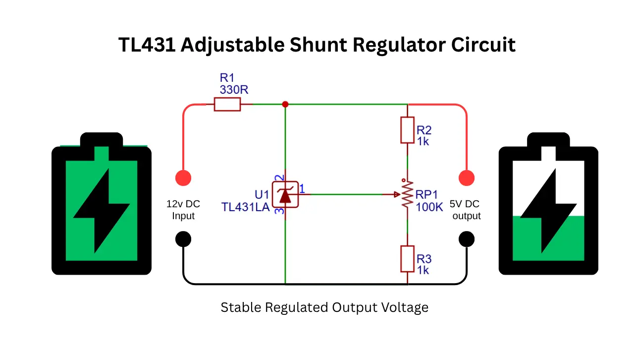
Using this TL431 adjustable shunt resistor circuit, you can easily regulate the unstable high DC voltage to stable DC output. With very less components we can get regulated supply voltage. This circuit is works based on this shunt voltage regulator to obtain the stable DC output.
What Is a TL431 Voltage Regulator Circuit?
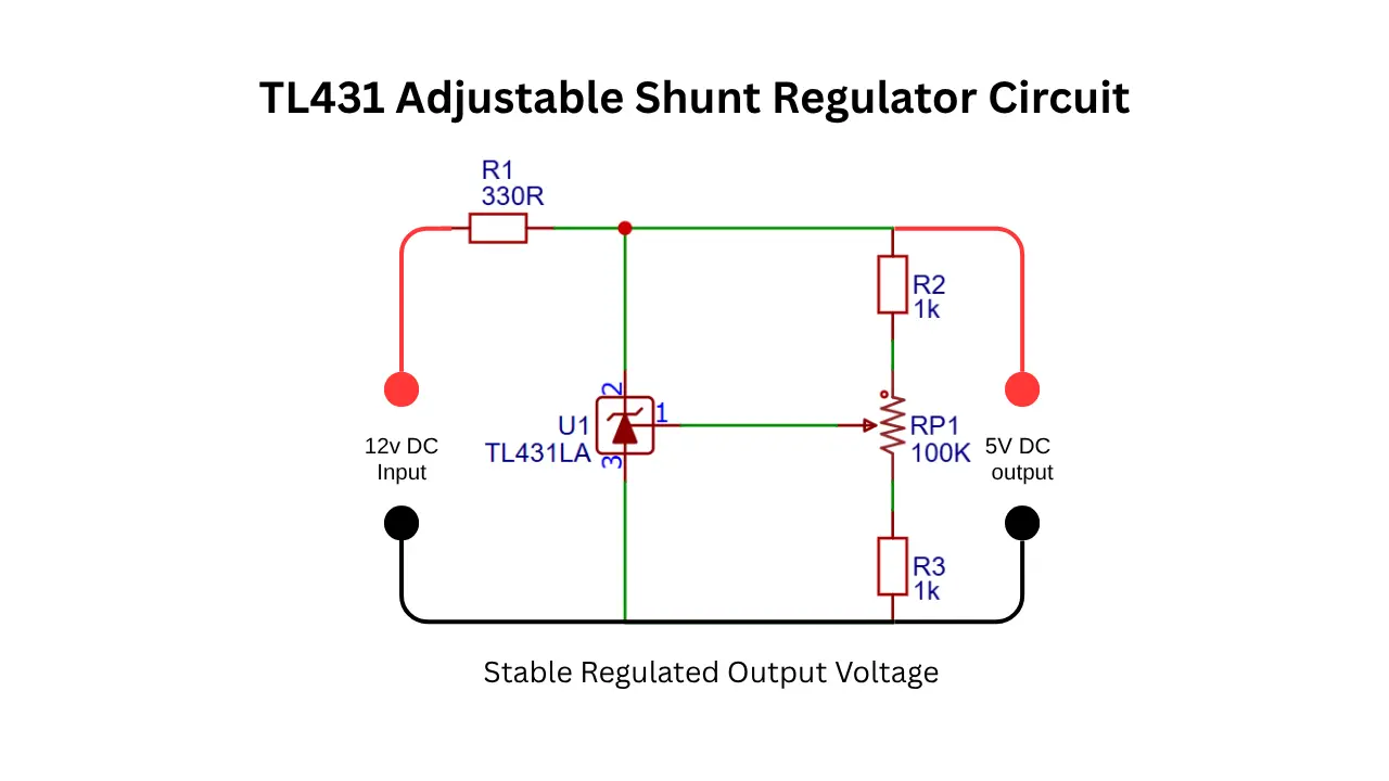
A TL431 voltage regulator circuit is an easiest way to get stable output voltage from an unregulated DC power supply. The TL431 is an adjustable precision shunt regulator that works similarly to a Zener diode but it offers much better accuracy and voltage control. This circuit using few external components of resistor and potentiometer.
You can set the desired output voltage by setting the pot value. The circuit is useful in power supplies, battery chargers, LED drivers and many other electronics projects. Because of its low cost, easy availability and excellent performance.
What This Circuit Doing?
- Input supply voltage is 12V DC.
- Output Regulated Voltage is 5V DC.
- The TL431 acts like a programmable Zener diode.
- The variable resistor used to adjust the output voltage.
- The 330 ohms resistor limits the current flow.
TL431 Adjustable Shunt Regulator Circuit Schematics
Components Required for the Circuit
- TL431 Adjustable Shunt Regulator (IC1) – 1 Piece
- 330Ω Resistor (R3) – 1 Piece
- 1kΩ Resistor (R1) – 1 Piece
- 1kΩ Resistor (R2) – 1 Piece
- 100kΩ Variable Resistor / Potentiometer (VR1) – 1 Piece
- 12V DC Power Supply (Vin) – 1 Piece
- Connecting Wires – As Required
- Breadboard or PCB – 1 Piece (for assembly and testing)
Role of Each Component in the Circuit
- The TL431 is the main component of the circuit, which continueously monitior the reference voltage and adjusts for a stable output voltage.
- The resistor R3 is a 330-ohm value 1/4 watt component which used to limit the current flow to the output and helps to create a voltage drop in the output.
- The resistor R1, R2, and VR1 is a voltage divider configuration which sets the output voltage at a stable level.
Limitations of TL431 Shunt Regulator Circuits
This simple circuit is suitable only for low current loads. For higher current loads a transistor or MOSFET must be added as a pass element.
Also Check : 12V DC motor protection circuit using TL431