In most of the cases when the battery discharges too much current, we can not identify. Because there is no indicator to show this. To solve the problem, we can design and use a 12V battery low-voltage indicator circuit using TL431. The circuit will continuously monitor the battery voltage. When the battery voltage falls below a preset level, the LED in the circuit will turn ON to warn that the battery needs charging or replacement.
What Is a 12V Battery Low Voltage Indicator?
When the battery voltage goes below the set value, the LED will start to glow. This indication alerts that the battery voltage is below the set value and stops discharging or using the battery, and recharges it and protect from damage reducing its life span.
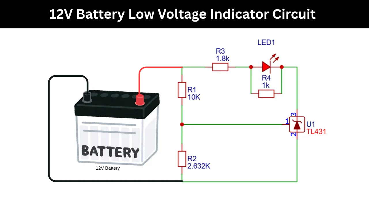
Circuit Diagram of the 12V Battery Low Voltage Indicator
Components Required
- TL431 Adjustable Precision Shunt Regulator – 1
- LED (Any standard 3mm or 5mm LED) – 1
- Resistor R1 of 10kΩ Resistor (¼W) – 1
- R2 of 2.632kΩ Resistor (¼W) – 1
- Resistor R3 of 1.8kΩ Resistor (¼W) – 1
- R4 of 1kΩ Resistor (¼W) – 1
- 12V Battery (Power Source) – 1
- Connecting Wires or PCB/Perfboard – As required
Purpose of Each Component in the Circuit
The TL431 is an adjustable precision shunt regulator. It acts as the main voltage detector. It continuously monitoring the battery voltage and internal reference voltage through the 10K and 2.632K ohms resistors.
These R1 and R2 resistor connected in series, and the output takes the middle connection of it it is called the voltage divider configuration. The 1.8 K ohms resistor is used to limit the current to the LED. The 1K resistor, parallelly connected with the LED, is used for biasing voltage for TL431.
Low Voltage Detection Threshold Calculation
The trip voltage of this circuit is using the formula of,
- where 2.5 is reference voltage.
- R1 is 10K ohms
- R2 is 2.623K ohms.
The warning level will be 12V. When the battery voltage falls below this The LED turn ON.
How to Set the Battery Warning Voltage
The battery warning level is determined by the two resistors of R1 and R2 changing the values will helps to increase or decrease the warning level voltage. To change the warning level,
- Increase R1 to raise the battery warning voltage.
- Decrease R1 to lower the battery warning voltage.
- Increase R2 to lower the warning voltage.
- Decrease R2 to raise the warning voltage.
Applications of the TL431 Battery Monitor Circuit
- Lead Acid Battery Monitoring.
- Solar Energy Storage Systems.
- UPS Battery Protection.
Also Check : TL431 Adjustable Shunt Regulator Circuit for Stable Regulated Output Voltage