The DC motors are working when you directly supply the DC voltage to it, everybody know this. But many peoples don’t think about its protection and how to increase its life. In this article I’m sharing a 12V DC Motor Protections circuit which will protect the Motor from Reverse polarity connection and Low supply voltage.
What is DC Motor Protection?
DC motor protection circuit is a specially designed electronic circuit to avoid the damage going occur to the motor. If the supply voltage is below rated voltage for the motor may damage its efficiency and reverse polarity may cause problems, so The protection board will solve all this problems.
How This Protection Circuit Protect DC Motor?
- The protection circuit is designed using a 1N4007 diode to protect the circuit and DC motor from accidentally connecting in wrong polarity. The correct polarity connection need to operate the circuit and turn ON the DC motor.
- The Voltage divider circuit is continuously monitoring the DC voltage, when the voltage goes below 11volt the relay cut off and protect the motor from working in low voltage.
If you want to check the voltage divider Vout. You can using our dedicated free online voltage divider calculator tool.
12V DC Motor Protection Circuit Diagram
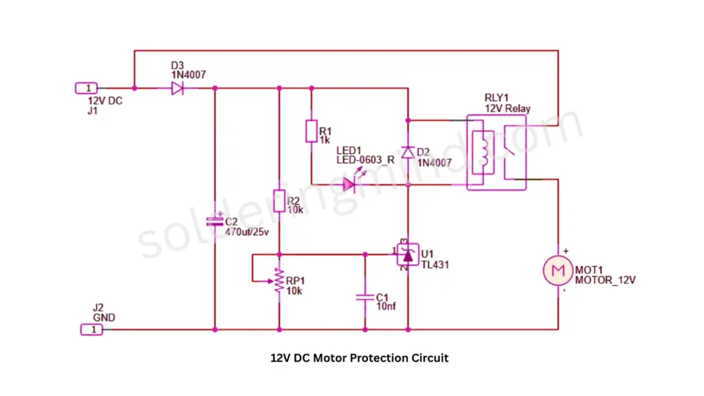
Components Required
| Sl. No | Component | Value / Part Number | Quantity | Description |
|---|---|---|---|---|
| 1 | Resistor (R1) | 1kΩ | 1 | LED current limiting resistor |
| 2 | Resistor (R2) | 10kΩ | 1 | Voltage divider / sensing resistor |
| 3 | Potentiometer (RP1) | 10kΩ | 1 | Adjustable voltage threshold setting |
| 4 | Capacitor (C1) | 10nF | 1 | Noise filtering capacitor |
| 5 | Capacitor (C2) | 470µF / 25V | 1 | Power supply filtering capacitor |
| 6 | Diode (D2) | 1N4007 | 1 | Flyback protection for relay |
| 7 | Diode (D3) | 1N4007 | 1 | Reverse polarity protection |
| 8 | LED (LED1) | LED-0603 Red | 1 | Status indication LED |
| 9 | Adjustable Shunt Regulator (U1) | TL431 | 1 | Voltage monitoring/control IC |
| 10 | Relay (RLY1) | 12V Relay | 1 | Motor switching/protection relay |
| 11 | DC Motor (MOT1) | 12V DC Motor | 1 | Load motor |
| 12 | DC Power Input (J1) | 12V DC Supply | 1 | Power source |
| 13 | Ground Terminal (J2) | GND | 1 | Ground connection |
Circuit Diagram Explanation
- The major connection of this circuit is TL431, voltage divider, relay and reverse polarity protection diode.
- The 1N4007 connected in forward biasing, it only conduct the current if the polarity of supply gives in correct manner.
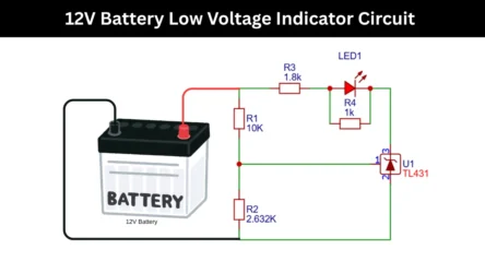
- The TL431 reference pin is connected with a voltage divider circuit and continuously monitoring the Supply dc voltage. Reference pin connected in the middle of 10K pot and 10 K resistor combnined connection.
Working Principle
- The 12V DC supply is providing through the pins of J1 and J2, The connected 1N4007 diode protect the circuit from Reverse polarity. The circuit only turns On in proper polarity of the supply connected.
- The capacitor 470uf is used to filter any unwanted signals from the DC supply and filter smooth Dc voltage.
- The TL431 continuously monitoring the DC voltage by using the voltage divider of 10K resistor and 10K potentiometer, adjusting the Pot will changes the cut off voltage.
- In normal condition supply voltage is 12V and the voltage divider gives enough voltage to Turn ON the relay and DC motor works.
Role of Relay in Motor Protection
The relay is act as the automatic switch for 12V DC motor. When all the working conditions are good the relay turns On and allow the current to pass through it and powering the DC motor.
When the supply voltage goes below 11 volt the TL431 cuts the supply to the relay and the relay contact detached and protecting the DC motor from low voltage sress.
Advantages of This Motor Protection Circuit
- Protects Against Low Voltage.
- Prevents Motor Overheating.
- The 10k potentiometer (RP1) allows users to set the desired cutoff voltage.
- It has a reverse Polarity Protection.
- By reducing stress the lifespan of motor increases.
Applications of 12V DC Motor Protection Circuits
- We can use it on Cooling fans, windshield whisper and fuel pump.
- Protect Solar DC pump.
- Helps safeguard DC motors in robotic systems.
- Hobby projects involving DC motors.
- automatic curtains and smart locks.
Limitations of the Circuit Design
- The circuit only protect from low voltage and reverse polarity not in case of short circuit and over current used by motor.
- The circuit uses relay, continuous operation damages the relay contacts. if short circuit occurs the relay contacts get burned.
- When the cutoff voltage level reached, the relay may rapidly switch ON and OFF due to small voltage fluctuations, potentially affecting stability.
- Not Ideal for High Power Motors.
Testing Procedure and My Observations
When connecting 12V DC to the circuit, it turns ON the LED and relay after that the DC motor starts to working. Purposefully I changed the supply voltage terminals then the circuit stops working, no LED indication. so the reverse polarity is working fine.
I am using bench power supply to power the circuit, after connecting supply i slowly reduce the supply voltage and the relay and LED turns off at voltage below 11V DC. Now the DC low voltage protection is also working good.