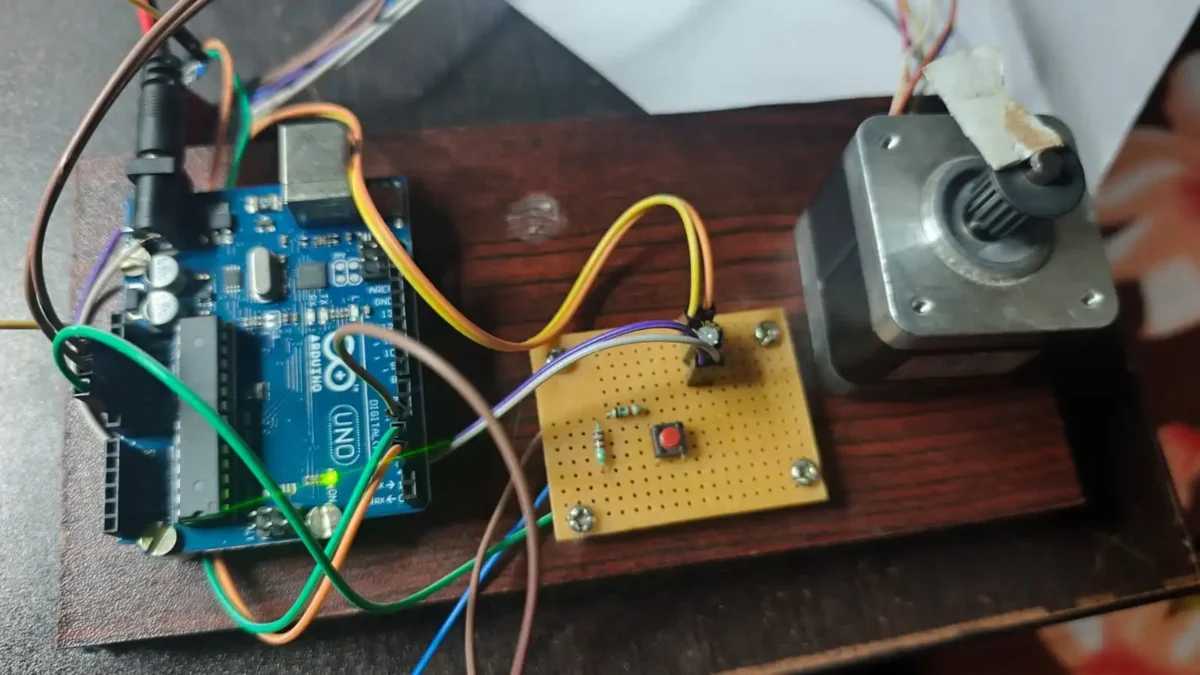
The Arduino-controlled stepper motor circuit is designed for a coil winding machine. When the push button is pressed, the stepper motor starts to rotating; pressing it again will stops it. The rotation also stops when the set number of rotations is reached. (stepsPerRevolution * 50) You can find in code.
Materials Required
- Arduino Uno
- A4988 Stepper Motor Driver Module (usually includes a small aluminum heatsink)
- Stepper Motor (im using Nema 17)
- External Power Supply (typically 12V DC, it is depending on your stepper motor’s requirements)
- Push Button Switch (momentary tactile button).
- 100 µF Electrolytic Capacitor (placed across the motor power rails to prevent voltage spikes).
- Breadboard (for organizing the circuit connections).
- Jumper Wires.
Arduino Stepper Motor Control Project Wiring Connection
Connection Details
- Arduino pin 2 connects to the A4988 driver’s DIR (Direction) pin. The Arduino digital pin 3 connects to the STEP pin, 5V to VDD, and GND to the common ground connection.
- The push button pin is connected to Arduino digital pin 4, and the other pin is connected to the Arduino ground pin. To reduce the noise, you can connect a pull-up resistor of 10K to the pin 4 connection and the other end of the resistor to 5V DC.
- The A4988 driver RESET pin and SLEEP pin are connected together and it connects to a 5V supply using a 2.2K resistor. If the RESET and SLEEP pins are connected and left floating (or connected to GND), the A4988 driver remains in the Sleep or Reset mode. This will disable the internal FET outputs. The motor will not receive power or take steps when your Arduino sends pulses.
- Stepper motor to A4988 driver connection is,
- Coil 1 Wire A > Connects to pin 1A.
- Coil 1 Wire B > Connects to pin 1B.
- Coil 2 Wire A > Connects to pin 2A.
- Coil 2 Wire B > Connects to pin 2B.
- The last is 12V power supply connect to VMOT, VDD and Arduino 12V connection points.
Programming Code Explained
// Define pin connections & motor steps per revolution
const int dirPin = 2;
const int stepPin = 3;
const int buttonPin = 4; // Connect button between Pin 4 and GND
const int stepsPerRevolution = 200;
This tells the Arduino digital pin 2 connected to DIR of A4988 and Pin 3 connected to STEP pin of driver board. stepsPerRevolution = 200; is the physical blueprint of stepper motor. To complete one full rotation needs 200 steps for Nema 17.
// Total steps for 50 revolutions = 200 * 50 = 10000 steps
const int totalSteps = stepsPerRevolution * 50;
This is the calculation part we set for 50 rotation then the code calculates the how many steps need to achieve 50 rotation by multiplying with 200 steps.
// Step execution (4ms total cycle = 250 steps/sec)
      digitalWrite(stepPin, HIGH);
      delayMicroseconds(2000);
      digitalWrite(stepPin, LOW);
      delayMicroseconds(2000);
    }
This value controls the overall speed of rotation. If value go high speed reduces and less means speed increases.
Speed Adjustment of Rotation Value
| Speed | Delay value | RPM |
|---|---|---|
| Very Fast | delayMicroseconds(600); | Approximately 250 RPM |
| Fast | delayMicroseconds(1000); | Approximately 150 RPM |
| My setup for coil winding | delayMicroseconds(2000); | 75 RPM |
| Slow | delayMicroseconds(5000); | Approximately 30 RPM |
| Very Slow | delayMicroseconds(5000); | 10 RPM |
Arduino & A4988 Stepper Motor Control: Button Start/Stop Programming Code
// Define pin connections & motor steps per revolution
const int dirPin = 2;
const int stepPin = 3;
const int buttonPin = 4; // Connect button between Pin 4 and GND
const int stepsPerRevolution = 200;

// Total steps for 50 revolutions = 200 * 50 = 10000 steps
const int totalSteps = stepsPerRevolution * 50;

void setup() {
  // Declare motor pins as Outputs
  pinMode(stepPin, OUTPUT);
  pinMode(dirPin, OUTPUT);

  // Configure push button pin with internal pull-up resistor
  pinMode(buttonPin, INPUT_PULLUP);
}

void loop() {
  // Check if button is pressed to start (LOW because of INPUT_PULLUP)
  if (digitalRead(buttonPin) == LOW) {

    // 1. Debounce and wait for button RELEASE before starting
    delay(50); // Debounce press
    while (digitalRead(buttonPin) == LOW); // Wait until finger is lifted
    delay(50); // Debounce release

    // Set motor direction clockwise
    digitalWrite(dirPin, HIGH);

    // 2. Rotate up to 50 full revolutions
    for (int x = 0; x < totalSteps; x++) {

      // Check if button is pressed AGAIN to interrupt/stop
      if (digitalRead(buttonPin) == LOW) {
        break; // Exit the for loop immediately
      }

      // Step execution (4ms total cycle = 250 steps/sec)
      digitalWrite(stepPin, HIGH);
      delayMicroseconds(2000);
      digitalWrite(stepPin, LOW);
      delayMicroseconds(2000);
    }

    // 3. Wait for release if the stop press is still active
    delay(50);
    while (digitalRead(buttonPin) == LOW);
    delay(50);
  }
}
You can download code and check small video demonstration from Solderingmind Github Gist