This Christmas light circuit diagram is a simple and very interesting electronic project. This circuit flashes the red and green led as a blinking light project. This blinking effect is very good for Christmas tree decoration and other festive occasion. The circuit uses a 555 timer IC and a few common electronic components. The IC continuously turns the 555 IC on and off, which makes the LED Turn On and off.
Christmas Light Circuit Diagram
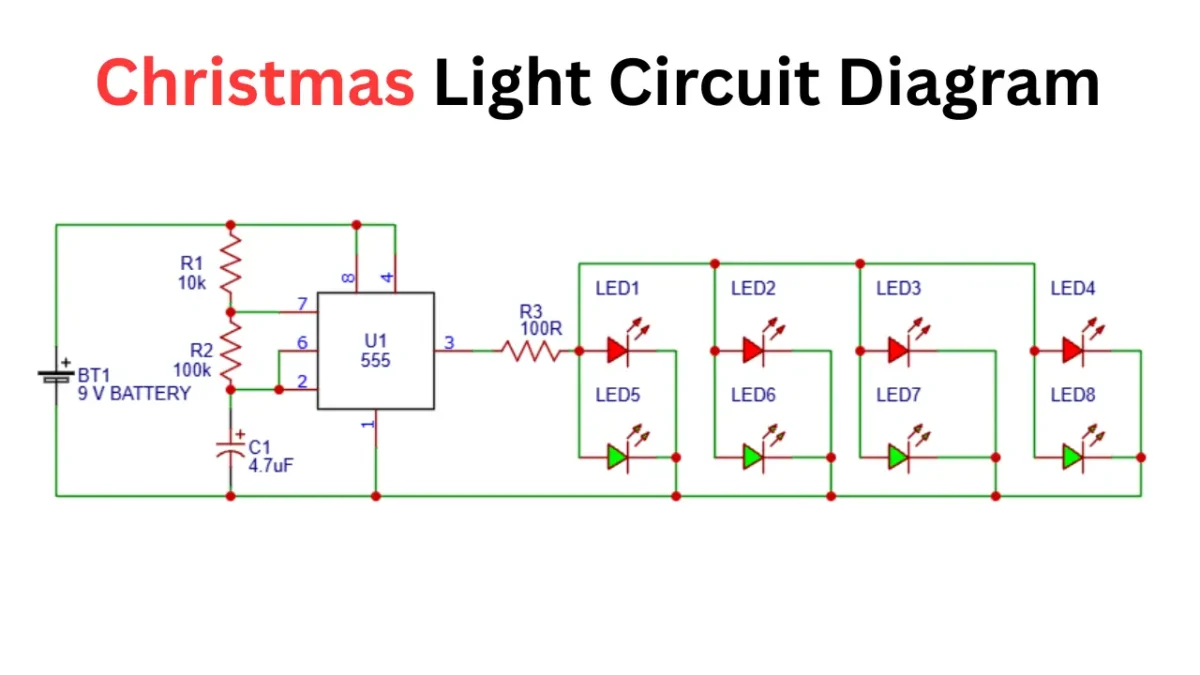
This circuit operates on a 9V DC battery. The circuit only requires a few connections to work. If you are building this circuit on a breadboard, it will look like a tiny LED blinking circuit. For decoration purpose i suggest you to add wires between the LED and make it long.
The circuit works in an astable mode. The timing components, including the capacitor and resistors, control the speed of LED blinking. The output pin of the IC controls the Blink voltage based on the frequency of turning on and off.
Components Required
| Component | Value | Quantity |
|---|---|---|
| 555 Timer IC | NE555 | 1 |
| R1 | 10KΩ Resistor | 1 |
| R2 | 100KΩ Resistor | 1 |
| R3 | 100Ω Resistor | 1 |
| C1 | 4.7µF Capacitor | 1 |
| LED1–LED8 | LEDs | 8 |
| BT1 | 9V Battery | 1 |
Circuit Working Principle
In this circuit, the 555 IC is the Main section. The circuit is configured in astable mode, which means the IC continuously generating the high and low pulses without any required external triggers. The resistor R1 and R2, along with capacitor C1 determines the frequency and speed of blinking LED.
When the circuit is powered, the capacitor gets charged, and when the capacitor charge reaches 1/3 of the supply voltage, the internal 555 comparator IC changes the state and activates the internal circuit.
Then the capacitor discharges and again repeat the cycle. This charging and discharging of the capacitor makes the square wave at the output of the IC. The connected LED in the output section turn On and OFF at specific intervals.
Pin Configuration of 555 Timer IC
| Pin | Name | Function |
|---|---|---|
| 1 | GND | Connected to the negative supply. |
| 2 | Trigger | Detects the lower capacitor voltage. |
| 3 | Output | Provides the blinking output signal. |
| 4 | Reset | Connected to positive supply. |
| 5 | Control Voltage | Controls the internal reference voltage. |
| 6 | Threshold | Detects the upper capacitor voltage. |
| 7 | Discharge | Discharges the timing capacitor. |
| 8 | VCC | Connected to positive supply. |
Function of Each Component
- The 555 Timer IC is the main control unit. Continuously turns ON and OFF and makes a pulse to drive the LED.
- Resistor R1 is 10K, connected to the positive supply and pin 7 of the timer IC. It provides the charging path for the timing capacitor.
- Resistor R2 of 100k is connected between pin 7 and pin 2,6 connection. It controls the charging and discharging time of the capacitor C1.
- 100R resistor is connected to output pin 3. This resistor is used to limit the current going to the LED from the 555 IC.
- C1 is the timing capacitor. It repeatedly charges and discharges, helping the 555 timer generate the required oscillating signal.
How to Calculate the LED Blinking Speed]
The blinking frequency of the 555 timer in astable mode can be calculated using the following formula:
Where:
R1 = 10KΩ, R2 = 100KΩ, C1 = 4.7µF
Important Note About the LED Connections
- In this circuit eight LED connected through the 100ohms resistor. If you want to add more LEDs, make some changes in the output section, like adding a Transistor to boost the voltage.
- The selection of current limiting resistor to the LED is based on the LED characteristics, forward voltage, and LED forward current.
Applications of the Christmas Light Circuit
- Christmas tree lighting decorations.
- DIY flashing LED projects.
- Decorative lighting for festive occasions.
- LED blinking experiments for beginners.
- Electronics learning and demonstration projects.
- Small battery-powered decorative displays.