I have a 1 watt LED and 12V power supply but i don’t know how to connect this LED and also has a doubt about the direct connection with battery? connecting the 1 watt LED directly to the high volt battery will leads to permanent damage of LED or reduce its life. So in this situation we need a specially designed LED driver circuit to get the maximum brightness and also increases its life. In this article i am sharing my simple transistor based LED driver circuit which can power the 1 watt high power LED using a 12V DC power supply. It uses three transistors of 2xBC557C and BC337. This transistor based circuit is a self oscillating boost converter that steps up the voltage to drive the 1 watt LED more efficiently than the direct connection with battery.
Components Required
| Component | Value / Part Number | Description | Quantity |
|---|---|---|---|
| R1, R2 | 10kΩ | Resistor, 1/4W | 2 |
| R3 | 1kΩ | Resistor, 1/4W | 1 |
| R4 | 470Ω | Resistor, 1/4W | 1 |
| R5 | 100Ω | Resistor, 1/4W | 1 |
| R6 | 1.5Ω / 2W | Power Resistor | 1 |
| C1 | 470pF | Ceramic Capacitor | 1 |
| C2 | 10nF (0.01µF) | Ceramic Capacitor | 1 |
| C3 | 100µF / 63V | Electrolytic Capacitor | 1 |
| D1, D2 | 1N4148 × 2 | Fast Switching Diodes | 2 |
| Q1, Q2 | BC557C | PNP Transistor | 2 |
| Q3 | BC337 | NPN Transistor | 1 |
| L1 | 10mH Inductor | Toroidal, 50 turns of 0.25mm wire | 1 |
| LED1 | 1W White LED | High Power LED | 1 |
| U1 | SPST Switch | Power On/Off Switch | 1 |
| B1 | 12V DC Supply | Battery or Adapter | 1 |
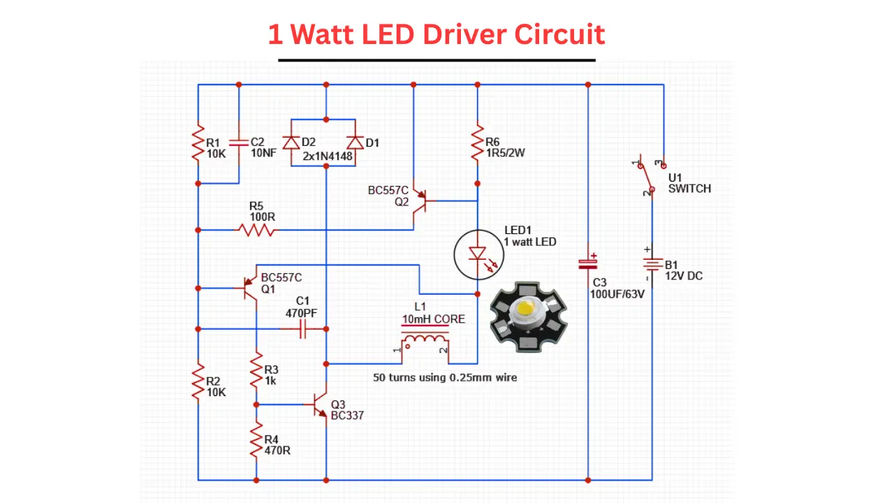
1 Watt LED Driver Circuit Diagram
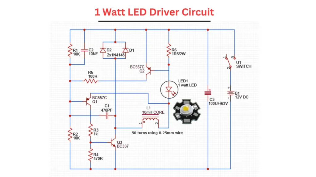
Connection Explained
The circuit is powering using a 12V battery or adapter. This 1 watt LED circuit is build with main three transistors of two BC557 and one BC337. This three transistor based configuration is acting like a self oscillating boost converter. The inductor is build with 50turns of 0.25mm wire on a 10mH ferrite core. The diodes of D1 and D2 is 1N4148 are fast switching diodes used for feedback and signal shaping. The capacitor C1, C2, and C3 are used for filtering, timing, and smoothing the power supply voltage. The resistors R1 to R6 set the biasing and current limiting levels in various parts of this circuit.
Working
When the circuit is powered using a 12V battery, the BC337 transistor is starts to oscillating due to the feedback coming from the Q1, Q2 and timing components of R3, R4and C1.
When the oscillation is occurred it will rapidly switches the inductor L1 ON and OFF. When the transistor Q3 is turns ON, the current will flows through the inductor L1 and it will storing the energy in its magnetic field. When Q3 is turns OFF, the coil releases the voltage stored in the inductor.
This high voltage drives the 1-watt LED, which requires a forward voltage of around 3.2V-3.6V and a current of ~300mA. The transistor Q2 and associated components of R5, D1, D2 is act as a feedback loop to regulate current to the LED and prevent damage.
The resistor named R6 of 1.5Ω/2W will limits the current through the LED and ensuring that it is working safely. The capacitor C3 of 100µF is smooths the ripples in the input power supply.