If you want to build an LED light circuit that directly powers from the AC voltage? To do this you need to build a Special AC LED driver circuit first. The 1 watt LED only requires 3 to 5 Volts and 350mA current to work perfectly. If you directly connect the LED to the AC supply it will explode or cause sudden damage.
So I am sharing this circuit for electronics hobbyists to do their own with proper guidance. This circuit consists of a few electronic components and a very low budget to build this circuit. Warning: The circuit is working in AC voltage so do the circuit testing with proper care.
1 Watt LED Pinout
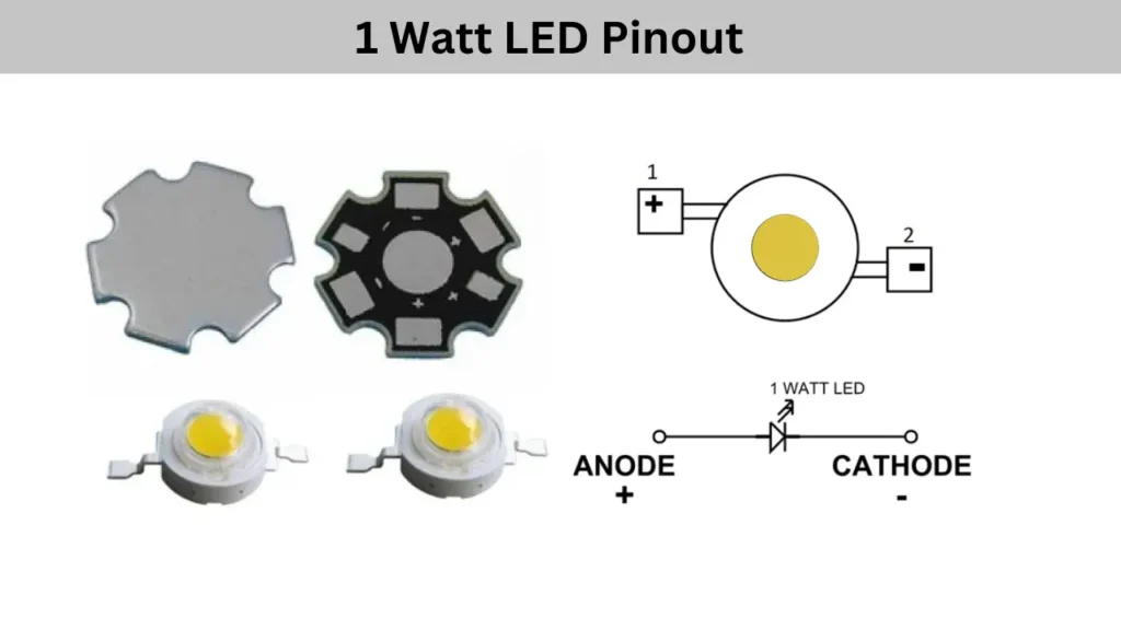
The 1 watt LED needs a working voltage of 3 volt to 5 volt DC. The LED working with low current 1 Watt LED will consume a maximum current of 350mA. Let’s check the pins of the LED light,
There are two pins available. The first pin is the Anode which is connected to the positive supply. The Second pin is the cathode which is connected to the negative supply of the DC source.
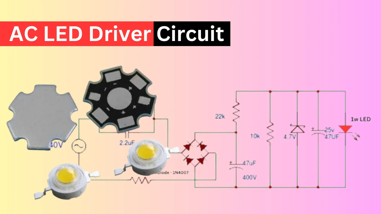
Circuit Diagram
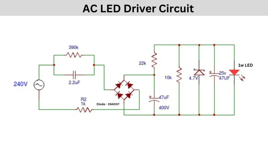
Components Required
- Electrolytic Capacitor (Non-Polarized): 2.2μF
- Resistors: 1KΩ, 10KΩ, 22KΩ, 390KΩ (four in total)
- Bridge Rectifier
- Zener Diode: 4.7V
- LED: Bright White LED
- Polarized Capacitor: 47μF
Working of AC LED Driver Circuit
This circuit is intended to work with an AC mains power source and provides a stable 4.7V DC output. The first step involves dropping the initial voltage using a capacitor positioned in series with the mains. A 390KΩ resistor is also connected across the capacitor.
Due to the resistor, the capacitor does not hold a charge when power is off. An additional 1k Ohm resistor is added before the rectifier to act as a fuse against power surges.
The initial output from the power source needs additional smoothing; hence, a 4.7μF capacitor is used. The 1.5A full wave bridge rectifier converts the AC into a more stable output.
Additional capacitors can further clean the DC output for use against the white LED. The LED would only light up when optimal power is delivered to the circuit. To finally regulate the output more to 4.7V, a Zener Diode is used along with a 22KΩ resistor that limits the voltage.