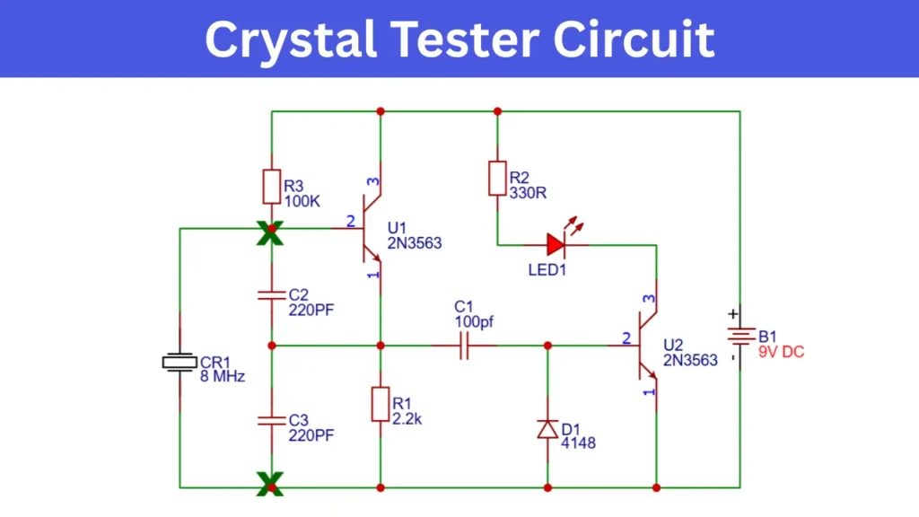
The crystal tester circuit is using to verify the quartz crystal component is working fine without any issues. The circuit consist of two Transistors and the crystal connecting to the circuit for checking. If the crystal is working good the LED turns ON and if not The LED stay in OFF state.
Crystal Tester Circuit Diagram
What Is a Crystal Tester Circuit?
The specially designed simple circuit to test the quartz crystal is working properly or not. If the crystal is working the connected LED turns ON and if it is fault the LED remain OFF state.
Why Crystal Oscillators Need Testing
The crystals are the stable clock frequency for the circuit. if it is fail means the circuit get damaged, so Before placing in to the main circuit, you can check the crystal is working or not. Proper checking avoids timing inaccuracy of the circuit.
Components Required
| Component | Value / Part Number | Quantity | Description |
|---|---|---|---|
| U1, U2 | 2N3563 NPN Transistor | 2 | High-frequency switching transistor |
| R1 | 2.2kΩ Resistor | 1 | Current limiting / bias resistor |
| R2 | 330Ω Resistor | 1 | LED current limiting resistor |
| R3 | 100kΩ Resistor | 1 | Bias resistor |
| C1 | 100pF Capacitor | 1 | Ceramic capacitor |
| C2 | 220pF Capacitor | 1 | Ceramic capacitor |
| C3 | 220pF Capacitor | 1 | Ceramic capacitor |
| D1 | 1N4148 Diode | 1 | Fast switching diode |
| LED1 | LED (Red or any color) | 1 | Indicator LED |
| CR1 | 8 MHz Crystal Oscillator | 1 | Crystal under test |
| B1 | 9V Battery | 1 | Power supply |
| Battery Clip | 9V Battery Connector | 1 | Battery connection |
| PCB / Breadboard | General purpose | 1 | Circuit assembly |
Working Principle of the Crystal Tester Circuit
- In this crystal tester circuit when crystal connected to the circuit creates an oscillation signal with the help of capacitor C2, C3 and Transistor U1. The connected quartz crystal is in good condition, it oscillates continuously.
- The capacitor providing the feedback and resistor provides biasing and gives stable oscillating output. The oscillating signal turns ON the second Transistor and which gives the LED indication as good Crystal and its functioning correct.
My Observations While Testing Different Crystal Frequencies
While testing the circuit I noticed that LED glow is varies based on connected crystal frequency. Low frequency crystal taking longer time to start oscillating and High frequency crystal gives stable LED indication.