The circuit is a simple adjustable linear power supply and it is designed to convert the 220V AC supply to a regulated 12V DC output. You can adjust the current and also it has short circuit protection. Many electronics enthusiast tried this circuit and working without any errors.
What the Circuit Does
- This power supply circuit performs diffent functions which are listed below.
- It converts the 220V AC to appropriate 12V AC using a step down transformer.
- Converting AC voltage to DC voltage using bridge rectifier.
- Smoothing pulsed 12V voltage to pure DC voltage.
- Regulates the output voltage using transistor based circuit.
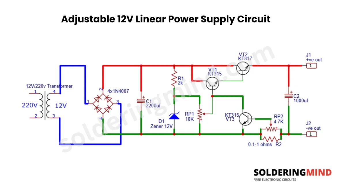
Adjustable 12V Linear Power Supply Circuit Diagram
Circuit Features
- Converts 220V AC to regulated 12V DC.
- Simple transistor based voltage regulator circuit.
- Adjustable current limiting.
- Short circuit protection.
- Low output ripple.
- Easy to build using commonly available components
- Suitable for bench testing and DIY electronics
Components Required
- T1 – 220V AC to 12V AC Step-Down Transformer
- D1 – Bridge Rectifier (4 × 1N4007 Diodes)
- C1 – 2200µF, 25V Electrolytic Capacitor
- C2 – 1000µF, 25V Electrolytic Capacitor
- R1 – 2kΩ, ¼W Resistor
- RP1 – 10kΩ Potentiometer (Voltage Adjustment)
- RP2 – 4.7kΩ Potentiometer (Current Limit Adjustment)
- R2 – 0.1Ω–1Ω, 1W (or Higher) Wirewound Resistor
- D1 (Zener) – 12V Zener Diode (1W Recommended)
- VT1 – KT315 NPN Transistor
- VT2 – KT817 NPN Power Transistor (with Heatsink)
- VT3 – KT315 NPN Transistor
- J1 – Positive Output Terminal
- J2 – Negative Output Terminal
- PCB or Perfboard – For Circuit Assembly
- Connecting Wires – As Required
- Heatsink – For KT817 Power Transistor
- Input Fuse (Recommended) – 500mA to 1A Slow-Blow Fuse for Mains Protection
Equivalent Components
For KT315 you can use BC547, BC337, or 2N2222 transistors. The KT817 is a power NPN transistor so you can use TIP41C, BD243C, or TIP3055 (with suitable heatsink). The VD1 od Zener diode is 12V, 1W Zener Diode (e.g., 1N4742A). The 1N4007 diode used you can use any equivalent of 1A, 1000V rectifier diode (if using four discrete diodes instead of a bridge rectifier).
Main Components and its function
The transformer is the main part of the circuit to convert the AC voltage to the appropriate 12 Volt AC voltage we need. This voltage will not be exactly 12V; it will vary based on the input AC voltage. Recommended to use a 220V AC to 12V AC step-down transformer for this circuit.
The Bridge rectifier is made up of four 1N4007 1A, 1000V diodes. This diode is used for low current application if you have a 3A transformer, you can use a 3A rectifying diode. This diode will rectify the 12V AC to pulsating DC voltage.
A 500uf electrolytic capacitor is used after the rectification. This capacitor helps to smooth the DC output voltage and eliminate the pulsating DC voltage. Difficult to find a 500uF capacitor; you can use a 2200uF or 1000uf 16 or 25V capacitor. There is no issue with using high-storage capacitors; it is good for proper filtering.
The 12V Zener diode is used for the reference voltage for the regulator circuit. It will be used as the reference voltage for the transistors to control the output voltage through the connected transistors.
The transistor VT1 is KT315, and it is used as a voltage amplifier or control transistor. The VT3 of KT315 is using to sense the current of the output. VT2 marked transistor is KT817; it is the power passing transistor. Which supply the regulated supply to the load.
How the Circuit Works
The transformer step down the AC voltage to a low-voltage 12V AC voltage. The rectifier rectifies the 12V AC voltage to 12V DC voltage, and the 500uF electrolytic capacitor smoothest the DC voltage. The connected Zener diode and 2K resistor give a reference voltage for the regulator circuit.
The transistor VT1 compares the reference voltage with the output voltage and controls the VT2 transistor. When the load current increases, a voltage develops across the Resistor R4; this makes VT3 start conducting. The transistor VT3 conducting means it reduces the output current by adjusting the VT2 transistor base voltage and limiting the overcurrent or in any short-circuit situation.
Additional Information Before Building This Circuit
This circuit can be directly connected to AC voltage through the transformer. So you need to take special care with the high-voltage AC. Build and test it only if you have enough experience with mains-powered equipment. Always use insulated wires and proper connections, with fuses as needed. If the power transistor heats up, please use an appropriate heatsink to allow the heat to dissipate.