In this article I’m sharing a useful electronic project for audio amplifier enthusiast. This is a Dual power supply board with multiple power output circuit. Which give Dual high voltage for amplifier, 15-0-15 and 5V DC outputs. You can get Downloadable files at the bottom of this article, enjoy.
Dual power supply Board PCB Layout
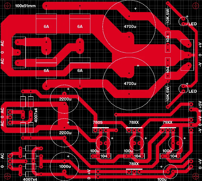
Using this PCB you can easily convert the AC voltage into DC voltage. Here you can see 3 section of Bridge rectifiers. The First one is uses four 6A diodes, which is used for main power supply for audio amplifier board like subwoofer amplifier.
The second bridge rectifier uses 1N4007 diode based, which is used for powering the stereo amplifier board. If you want more current replace the 4007 diode with high ampere diodes.
The third bridge rectifier is for any other voltage needed for the amplifier section like cooling fan or clipping detector circuit board.
35 Ampere, 4x10000uF/63V Dual Supply Metal Case Bridge Rectifier & Filter Board with Auxiliary Supplies 5V, 12V, 12-0-12V. (For High Power Amplifiers& Sub Amplifiers) AC Up to 44-0-44 Volt
- Maximum Input AC voltage 44-0-44 Volt AC, Maximum Current 35 Ampere, 4 x 10000 Micro Farad, 63V Capacitors, Regulated 5V & 12V & Unregulated 12-0-12V, No Soldering Required, Easy To Install Using Pins & JST wires, Heavy Duty Connecting Terminals and Premium Quality FR4 PCB
As an Amazon Associate, I earn from qualifying purchases.
🔥 Check Price on AmazonComponents Required
| Sl. No | Component Name | Value / Specification | Quantity |
|---|---|---|---|
| 1 | Bridge Rectifier | 4007 x 4 (1N4007 diodes) | 8 (2 sets) |
| 2 | Electrolytic Capacitor | 4700µF / 25V (or higher) | 2 |
| 3 | Electrolytic Capacitor | 2200µF / 25V (or higher) | 2 |
| 4 | Electrolytic Capacitor | 1000µF / 25V (or higher) | 1 |
| 5 | Electrolytic Capacitor | 100µF / 25V | 4 |
| 6 | Ceramic Capacitor | 104 (0.1µF) | 4 |
| 7 | Voltage Regulator IC | 7805 | 1 |
| 8 | Voltage Regulator IC | 78XX (e.g., 7812 / 7815 depending on design) | 1 |
| 9 | Voltage Regulator IC | 79XX (e.g., 7912 / 7915) | 1 |
| 10 | Resistor | 10K 5W | 2 |
| 11 | LED | Standard Indicator LED | 2 |
| 12 | Diode | 6A | 4 |
| 13 | Terminal Block / Connector | AC Input | 1 |
| 14 | Terminal Block / Connector | Output (+V, -V, GND) | 1 set |
| 15 | PCB | 100 × 91 mm | 1 |
Working Principle
The working principle of this rectifier based power supply board is very simple. The input AC signal is converted to DC voltage. The 4700 uf capacitor is further filtering the output voltage and providing a linear DC supply at the Output connection.
78xx is marked for your conveniences, you can use 7812/7912, 7815/7915 the decision is yours. You can select the numbering based on your amplifier specifications.
Applications
- Power supply for Amplifier
- Used for Subwoofer amplifier.
- You can used this board as Lab bench power supply.