If you are planning to build a simple audio amplifier circuit? But the audio board need a proper Dual power supply board to work efficiently without any humming or distortions. So i decided to share the circuit diagram and PCB Layout of Mini DC dual power supply board for amplifier projects. You can download the files and build your own PCB at home.
Dual Power Supply Board Circuit
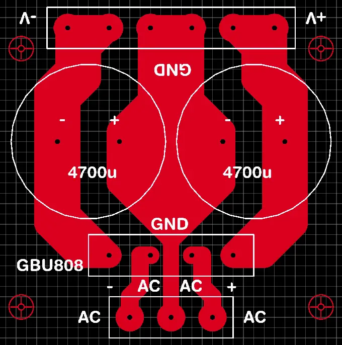
This Mini power supply board consist of very few number of electronic components. The GBU808 is used in this circuit to avoid large PCB length. if you are using 10A diode the board become larger. The 4700 electrolytic capacitor is used in this circuit is 25V rated.
If you want to add more changes needs to make in the PCB. If the 63V capacitor may not suitable for this PCB because the Capacitor legs distance is different based on the voltage ratings and capacitor values.
Components Required
| Sl. No | Component Name | Specification / Value | Quantity |
|---|---|---|---|
| 1 | Bridge Rectifier | GBU808 (or similar) | 1 |
| 2 | Electrolytic Capacitor | 4700µF (high voltage rated) | 2 |
| 3 | PCB Terminal Block (AC) | 2-pin or 3-pin screw type | 1 |
| 4 | PCB Terminal Block (DC) | 2-pin screw type (+, -) | 1 |
| 5 | PCB Board | Custom PCB (as shown) | 1 |
| 6 | Mounting Holes / Screws | For fixing PCB | 4 |
This PCB layout tracks are very thicker and maximum area is given for efficient current flow. The Bridge rectifier can handle up to 8 Amps, so a thicker track is needed. Additionally you can add 104pf capacitors in the output and input voltage sections to rectify high frequency noises.
I think adding LED to this circuit board will look like neat and visually identify the output voltage is coming or not. I want to redesign this circuit with more advanced power supply later, but still it is for a mini amplifier board then it is enough.