While working with electronic circuits or electronic devices an external power supply is needed to check if it is working or not. But the main problem is that different devices have different input voltages . In this situation the voltage Adjustable Lab Bench power supply has an important role. In this post I am sharing the Dual DC Bench Power Supply Circuit Diagram and also explaining the working of it.
Introduction

The Bench power supply is one of the helpful electronic devices for those who are testing or repairing electronic devices. You can control the output DC voltage and Current using a potentiometer or push button. Most of the advanced .Lab Bench power supplies come with a seven segment display and a controlling knob.
What is Bench power supply?
Converting the AC voltage to DC voltage and using it for the power source of testing electronic devices. The device output DC voltage is adjustable and you can set it by using the potentiometer. From the power supply the set voltage and current will remain stable.
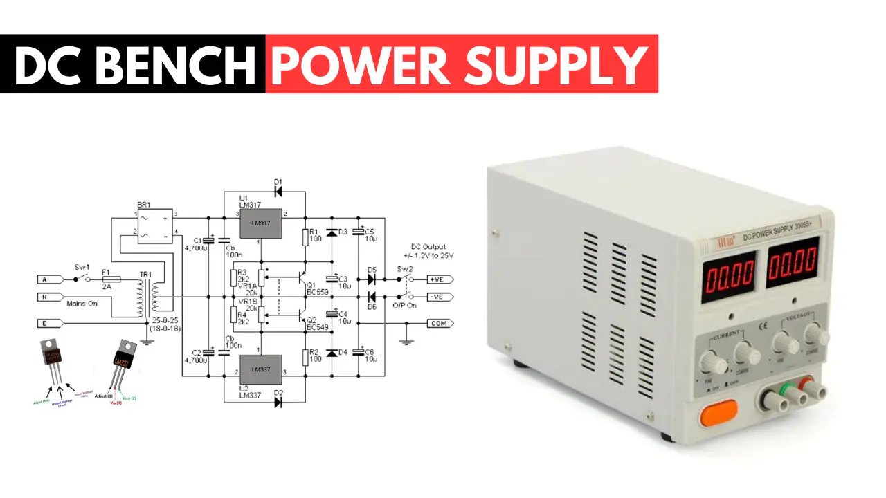
DC Bench Power Supply Circuit Diagram
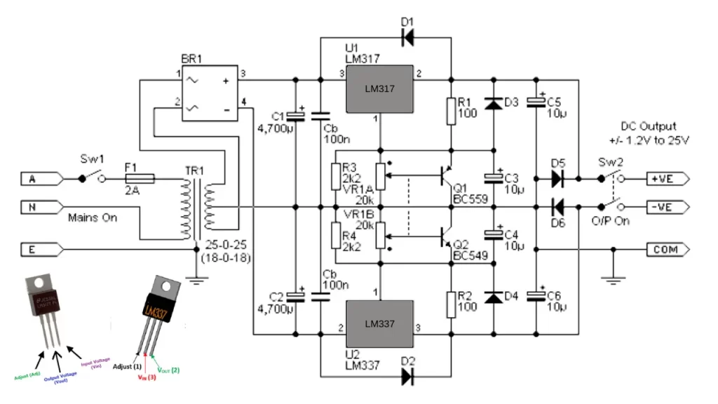
This power supply is based on the IC LM317 and LM337 variable three terminal regulator IC. The maximum output from this dual supply circuit is about +/- 25V. You can adjust the output voltage by rotating the potentiometer connected with the IC circuit.
This circuit is enough to test most of the electronic circuits like preamp and power amplifier circuit. Make sure you mount an aluminum heatsink on the both regulator IC to avoid overheating.
The diode D5 and diode D6 is 1N4007 and it is used for the protection features of this circuit, the diode will prevent the external reverse voltage to the circuit. You can use the 18-0-18 V 2A transformer for this circuit.
Components Required
| Component | Name | Quantity |
|---|---|---|
| Transformer | 18-0-18v 2A transformer | 1 |
| Regulator IC | LM317, LM337 | 1, 1 |
| Bridge rectifier | _ | 1 |
| Capacitor | 4700uf, 10 uf, 100nf | 2, 4, 2 |
| Diode | D1 to D6 (1N4007) | 6 |
| Resistor | 2K2 | 2 |
| Dual gang potentiometer | 20K | 1 |
| Switch | – | 1 |
Working
The 25 v transformer is connected to the Ac. When the power is connected the 25-0-25 v AC goes to the bridge rectifier input section and rectifies the AC voltage to 25V dual power supply.
For more filtration process two 4700 uf electrolytic capacitors are connected. After filtration the dual voltage goes to the regulator IC input. The positive voltage is connected to the LM317 IC pin number 3 and negative supply to the IC LM337 pin number 2.
The BC559 and BC549 transistors are connected to the 20K potentiometer for fine tuning. You can use a dual gang potentiometer to control the voltage in dual power supply. The output voltage will be adjustable from +/-0.7v to +/- 25v DC.
Conclusion
This dual bench power supply will help you in most of the situations. The circuit is tested and working perfectly. You can use it as a portable bench power supply. Build this circuit inside a cabin for more attractiveness. You can also add voltage indicating a seven segment display for accurate reading; this is optional. See you in the next power supply circuit, bookmark this page if you like this project.
🎁 AlsoCheck: Other Power supply circuits
FAQ
Converting AC voltage to DC voltage and useful for delivering stable voltage and current for testing or repairing the elevtronic device.
The bench power supply works through diffrent stages like AC to DC conversion, Rectification, Voltage regulation and output voltage protection. The AC convert to DC voltage with the help of rectifier and the voltage is goes to the voltage regulator. The connected potentiometer determine the output voltage. after that the output voltage is passing through the short circuit and other protection circuit.
AC voltage is converted to the DC voltage using a step down transformer, rectifier and capacitor is called as DC power supply.
The variable power supply is user can adjust the output voltage and current using the potentiometer or switch.