In various conditions, the grid line voltage will fluctuate and it will kill our home appliances and also reduce the life of any electronic systems. In this case, we can not know at which time the voltage fluctuations happen. Normal home appliances like Toaster and televisions will not withstand in higher voltage. so I’m introducing a simple electronic circuit breaker circuit for you.
This circuit breaker project works based on the IC LM358 op-amp. This entire circuit diagram will continuously monitor the input AC voltage in any cases of Over voltage or Under voltage the circuit will trigger the Relay to turn off the connected devices.
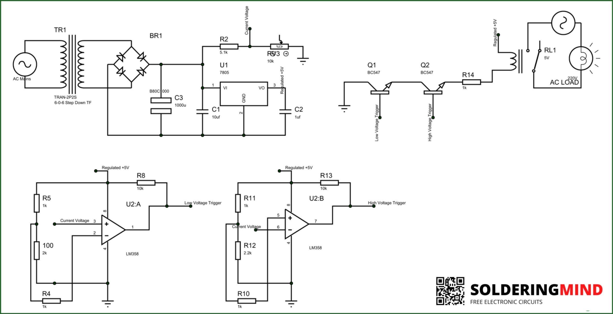
Electronic Circuit Breaker circuit
The Complete Schematic diagram of the Electronic Circuit Breaker is given below. Read further for to know the working and its explanations.
Components Required
- LM358 ( Dual op-amp IC )
- 7805 ( 5v voltage regulator )
- 12v Stepdown Transformer
- 5V Relay 10amps
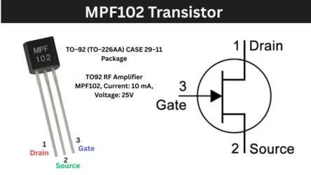
- BC547 Transistors ( 2 Nos )
- 10K pot
- 1K,2K,2.2K,10K and 5.1K Resistor
- 0.1uf, 100uf, 10uf capacitor
- Bridge Diode
- Connection wires
Electronic Circuit Breaker Working
As shown above circuit diagram The simple electronic circuit breaker, Really contains a few numbers of electronic components in this circuit diagram. i am explaining the working of each of part in the circuit diagram below.
Input Power Supply Section
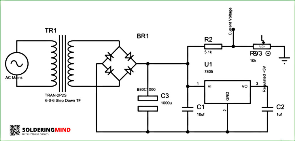
LM358 is the heart of this circuit diagram. so we need a regulated power supply to turn on it. so a 12v transformer is used to provide continuous 12v DC then it will regulated to 5V.
- So the above circuit will clarify that the transformer will convert 220v AC to 12V AC supply.
- Then the 12V AC supply has to be rectified through the combination of a 1N4007 bridge diode and a 1000 uf filtering capacitor.
- Then the 12v DC injected to LM7805 Ic will be converted into 5V DC for LM358 IC supply.
Op-Amp Circuit
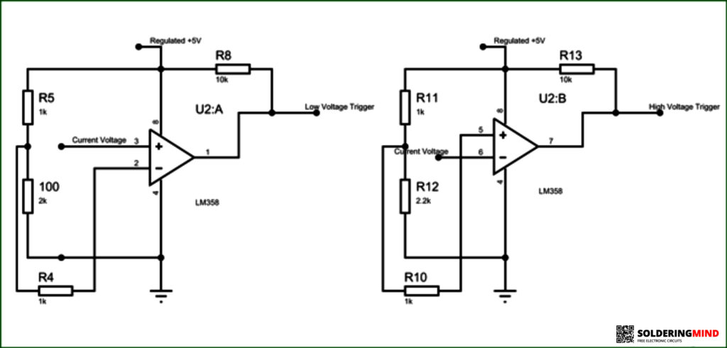
In this Op-Amp circuit section, a total voltage comparison is occurring. The two subdivisions of op-amp are noticeable. One section is used to compare the ” current voltage ” and the other one is compared to the “low voltage value”. both sections are shown in the above image.
The voltage comparator in this case the voltage between the pin 3 and 2 is comparing. If the voltage of pin 3 is greater than the voltage of pin 2 then the output voltage of the op-amp section is high like the output voltage is 3.6v, else the output voltage will be zero.
In this circuit diagram, the low voltage cut-off is set by 1K and 2K resistors. Also, the high voltage threshold is set by the Pin 5 using 1k and 2.2k resistors.
Relay Control Section
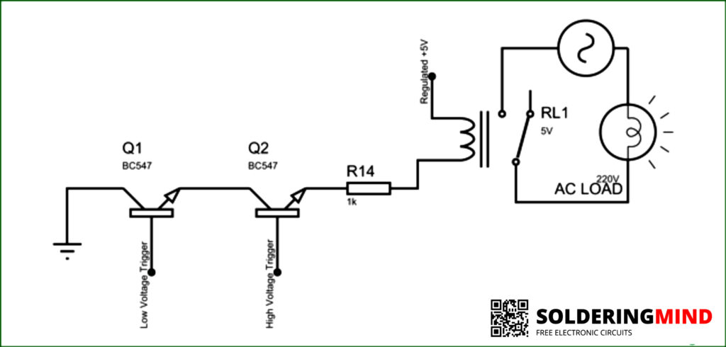
If both op-amps will operate the relay circuit. In the case of Low voltage and High voltage conditions, the op-amp will trigger the voltage signals and it will turn off the BC547 transistor. In that condition, the home appliances will be protected. Once you understand the workings of this circuit it is not a problem to build your own.