This is a simple three transistor wireless AC line detector circuit and PCB layout project. The circuit will work when it reaches the side of any electricity passing device or wire. the basic principle is based on the radiated energy from the electrical or electronic equipment. so in this article, I am going to share an idea of how to make an AC line detector circuit.

Working
The working principle of this wireless ac line detector is very simple to understand. it’s working based on the radiated energy from the ac source. that means the AC ( alternative current ) passing through a wire makes a magnetic field around the wire. That will possess some charges on the magnetic field when the charges come contact on the antenna of the circuit, then the circuit will work and turn on the LED ( glowing LED ).
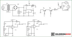
AC Line Detector Circuit Diagram
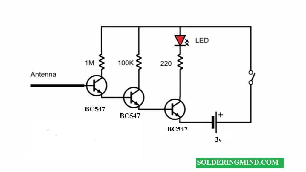
The circuit contains three BC547 transistors. A first transistor which receiving the signals through the base pin of the transistor. If any signal gets the transistor will pass a charge through the emitter pin and reaches the second BC547 transistor and verifying the strength of the signals. and again the voltage passes through the transistor then reaches the third transistor and it will turn on the led.
MX AC Line Fault Detector Socket Tester 5A | Electrical Socket Wiring Tester with LED Indicator | Detects Live, Neutral & Earth Faults | Plug-in Earthing Connectivity Checker
As an Amazon Associate, I earn from qualifying purchases.
🔥 Check Price on Amazon