Lets Buid a perfect and simple LED Chased Circuit using CD4094 IC. You can attach 8 LEDs in this circuit. Adjusting the potentiometer of 5K will increase the speed of running LED. This is a very interesting project for hobby electronics enthusiasts.
To build this simple project, you need only a few numbers of electronic components such as 2 IC and some resistors and a transistor. I personally tested it and it is working perfectly and the project is completely tested OK.
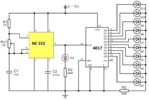
Simple LED Chaser Circuit Diagram Using NE555 and CD4094 IC

In this circuit the clock pulse is generated by the timer IC of NE555. The timer output is provided through the pin number 3 of the IC. The clock signal is injected inside of the CD4094 IC by using a 1k resistor.
When the 5K potentiometer is rotating the output frequency of the signal is changed and the spread of the running LEds will vary.
A J2 (jumper) is connected between the pin CD4094 IC 15 and 2, and the pin number 15 and 2 is connected to the positive supply using 1K resistors. The jumper acts like a switch. When the jumper is attached the circuit works in a stable mode and the jumper is detached the LED will glow like running.
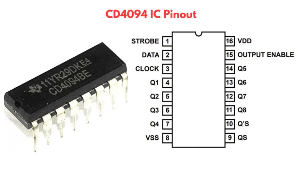
CD4094 IC Pinout
Components Required
- CD4094 IC -1
- NE555 timer IC -1
- 2SC1815 transistor -1
- 5K pot -1
- 1K resistor -4
- 1N4007 diode -1
- 560 R resistor – 8
- 1000uf/25v capacitor – 1
- 470uf/25v capacitor – 1
- jumper pin or wire – 1
Lets build this beautiful LED chaser circuit using the above guide. The complete detailes about circuit making is given here. please share your valuable comments to encourage me to share more interesting posts with you. Thanks.