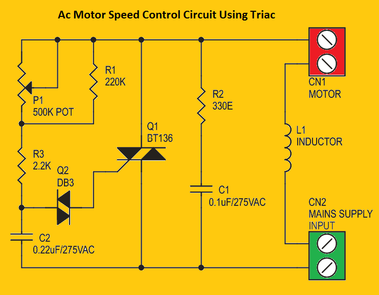
This is a BT136 Triac based 230-volt AC motor speed control circuit and it is designed for adjusting the speed of an electrical motor in your home, like a drilling motor or dress stitching machine motor. The speed of the electric motor was adjusted by using the Preset pot on the circuit diagram.
- Also, check How to connect an LED bulb directly to AC
So in this article, I’m going to explain in detail how to control the electric motor speed control using Triac based circuit. The specialty of this circuit is very few numbers of components are used to control the power AC motors.
BT136 Triac Pinout
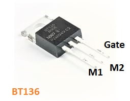
- BT16 triac
- M1 – Main Terminal 1
- M2 – Main Terminal 2
- G – Gate of the Triac
BT136 Motor Control Circuit
- Also, check AC line detector circuit
The motor speed control circuit works based on the Triac of BT136. Adjusting the 500k pot will increase or decrease the running speed of the electric motor. The Inductor used in the circuit is optional you can use or avoid it ( you can also take the direct neutral without the inductor ).

I will tell you after I studied about that