This class D amplifier circuit is based on IR2110 ic. The power output is up to 900w with HiFi audio quality. The circuit diagram and PCB layout are available here.
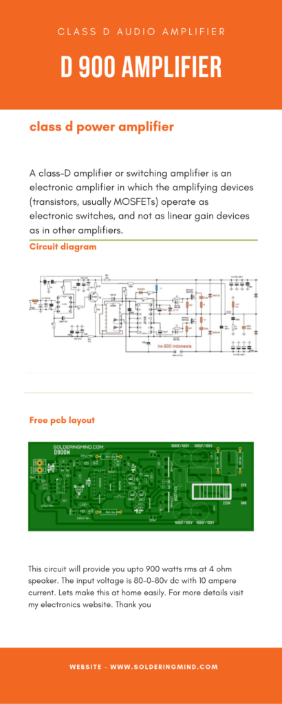
This is a class D amplifier mono board, you can build these two mono board to make power stereo class D amp. The stereo setup will give you up to 1800w power output. This circuit is the best ever circuit who are loving class D amplifier. So, in this article, I’m going to explain how to build an amplifier at home easily.
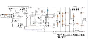
This class D amplifier design consist of three ic are TL071, CD4049, and IR2110. The combinations of these components will produce high-quality audio outputs in the output stage.
900W Class D amplifier circuit diagram
Click on the circuit diagram to view in high resolution
Components required
- TL071 IC – 1
- CD4049 IC – 1
- IR2110 IC – 1
- 10UF BIPOLAR CAPACITOR – 1
- 100K RESISTOR – 2
- 1N4148 DIODE – 5
- 2K2 RESISTOR – 1
- 1NF CAPACITOR – 3
- 1K RESISTOR – 2
- 10 OHMS RESISTOR – 6
- 100 NF CAPACITOR – 4
- 2N5401 TRANSISTOR – 1
- 330 UF CAPACITOR – 2
- 22OUF CAPACITOR – 1
- 4K7 RESISTOR – 3
- 8K2 2W RESISTOR – 2
- 100UF CAPACITOR – 3
- 5.6V ZENER DIODE – 2
- 12V ZENER DIODE – 1
- MUR 120 DIODE – 2
- MUR460 -1
- 220 PF CAPACITOR – 1
- 22UH INDUCTOR – 1
- 1K5 2W RESISTOR – 1
- 10r 2W RESISTOR – 1
- 680NF / 300V CAPACITOR – 1
The inductor coil using in this circuit
The inductor coil is the main part of this circuit diagram. So don’t ignore this part. Using the correct value and correct inductance will give you the maximum peak of the output range. you are using any kind of toroidal core. This concept is wrong because the inductor carries high current so the inductor needs the high current capacity to work perfectly.
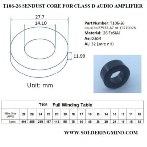
So I recommended you to you say a sendust toroidal Core. The toroidal core number is T106. This kind of toroidal core can withstand high current and high temperature. The normal for its core and the iron core will saturate fastly comparing with the SENDUST CORE.
The inductance is 22 micro Henry. The tents it is changing according to the type of toroidal core or you are using so please use an LC meter to confirm the micro Henry is correct
D900 PCB layout
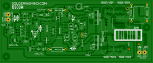
D900 PCB layout and components silkscreen
Power supply for class d audio amplifier
The power supply he is provided at least 70 to 90-volt dual power supply. I recommended to do not use over-voltage, this will damage your components in the amplifier board.
Use the recommended voltage as per circuit diagram. Buying a transformer of 90-volt power supply will cost you the highest amount. So in my suggestion use and SMPS with volt power supply. The SMPS will reduce the space requirement of the amplifier.
Now a days the class the audio amplifier is getting more popular then other kinds of audio amplifier systems because of the specification of this audio amplifier. The audio amplifier board is very small as compared with the class A, Class A B, class B.
And the lowest price is the the important factor in class D audio amplifier. Low heat dissipation and the space requirement is very low that is the advantage of this D class power audio amplifier.

I need 500w at 4 ohms output from this circuit .how much dc volt need
i need 700 warr rms class D amplifier.
D900 is available use it
900w amplifier is why not use the ocp protection circuit.
Please help me I made this circuit but not working
Check all connections properly
I makes the circuit I’m testing it at 15-0-15 but there’s no pulse at low side only high sid e pulse please help me
can u pls explain supply connections, about -ve suply. is ir2110 given dual supply?
Do you have the Gerber files for this. Converting the PDF files do not work. I just need to get the PCB’s made.
Regards.
Sir I use irfp250 MOSFETS in this circuit,how much of RMS power it produce
Can I use 15inch 400w speaker at 8ohms impedance
can you tell me what component that is on your pcb layout that has a circle and A C text, it is located in the top middle of the layout and connected with 10k resistor. I’m just a newbie and i want to make this class d amp. I already googled it and didn’t find the answer since you made the layout maybe you can tell me what it is.
Thank you so much for doing the remarkable job here,
everyone will like your post.
Best regards,
Harrell Dencker
HELP
15K > 47K
Are the parts already updated? Thanks so much.
Can i use 45 to 60 volt dual power supply for this circuit..
sure
Thank u
thanks buddy
essa placa tem ela no mercado pra vender amigo
OK meu amigo
I made the stereo very smart and the powerful amplifier is all right by making some changes. Thank you very much for uploading it
THANKS FOR YOUR COMMENTS MY FRIEND.please provide what are the changes you made. its helps others also
Dear friends with apologies You have misplaced some parts ir2110 will require 22uf instead of 100uf The 12v bias will require 220uf instead of 100 uf +/- 5v and tl 071 will look 100uf which you have installed somewhere 15k resistances will be replaced by 47k Correct them too. I have done very well now The bass is also very powerful
thanks for sharing this ideas it will helps others too
mosfet Ok don’t burn now this time But the sound was not clear irfp260n not the reason ??
Dear friends with apologies You have misplaced some parts ir2110 will require 22uf instead of 100uf The 12v bias will require 220uf instead of 100 uf +/- 5v and tl 071 will look 100uf which you have installed somewhere 15k resistances will be replaced by 47k Correct them too. I have done very well now The bass is also very powerful
what is A and C its marked in circle but didn’t mention component name or value.. please inform me
this not A and C its an led With anode and cathode legs
Yes this is yours lay The problem of heating the mosfet was solved 1n4007 is normal speed diode and mur120 is ultra high speed Now I have removed 1n4007 And installed mur460. next issue of sound is not Clear What to do with it
i think you resolved your major issues. still the mosfets burn out or not
I’ve used irfp260n with 65 + 65 power supply mur120 replace to 1n4007 diode Not doing all this work increases the volume so the mosfets get burned Brother, tell me a solution
are you using my layout or not , do you use the correct inductor coil
My circuit is not working can you help me
Explain it
Coil formula tell me in standard wire gauge Not in american wire gauge
There is no available irfp4227 and mur 120 diode in our market
this circuit work well?
You need to use proper conductor coil
OK I started making it It would be much easier to share a picture or video of a full board on a page
900 watt class d nice
thanks deepak
pcb lay out size?? Irfan
15 cm length and 6cm width
this circuit 900w class D work well and tested??
I need 1500 watt class D amplifier pcb layout
Thanks for sharing information
you are always welcome my friend
I need 1500 Watt class D amplifier pcb layout
check the link and download