The simple continuity tester circuit is based on a few components. The beginners can also build the circuit easily. The circuit is constructed with single NPN switching transistor of SL 100 ( you can use any type of NPN transistor instead of SL100 transistor ). Bc 547 can also use. This circuit will give visual ( lighting an LED) and audio output ( beep sound produced by the piezo buzzer) when the continuity present at the probs.
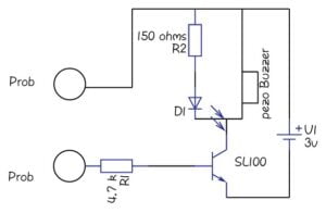
Circuit Diagram
Construction and working details of this circuits
Here the NPN transistor switching characteristics are used to detecting the closed continuity of the circuit. The SL100 transistor collector terminal connected with a positive 5 volt supply through buzzer and LED. The emitter terminal directly connected to the batteries negative terminal.
The base terminal act as the prob when the minimum bias occurred, that means 0.7 volts arrives at the base in the sl100 transistor will act as a closed switch then LED and the buzzer will give output by the way we can get to know about the continuity between the two probs.
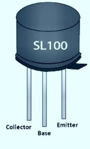
SL100 Transistor Pinout
Continuity Testing
You want to check the continuity in a circuit, first, you need to take the two probs from the circuit. one prob at the circuit terminal and touch the other prob where you want to check the continuity. Is the continuity is good for the circuit then you get the indications of glowing the LED with the beep sound of a piezo buzzer.
How the continuity tester works?
The continuity tester is an electronic device that tested the equipment used to determine if the electrical part can be established between two pins that are if an electrical circuit can be made. The continuity tester contains two props when the two crops contact with each other that shows the visual and the audio indications. is the audio and the visual indications are present we will conclude that the circuit having a good continuity.


I made a circuit but it makes sounds even without testing for wire
However I used 1k ohm resistors 2 of them and bc547
Thanks for your valuable comments