Using ic 7805 voltage regulator circuit – nowadays most of the microcontroller projects needs a minimum voltage of 5 volts. Mostly the 5 volt supply is provided by a regulator IC of 7805. Picture past package free pin positive voltage regulator. Which will provide you the continuous 5 volt supply along with one ampere.
Circuit Diagram
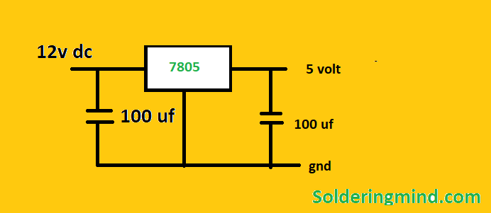
The single 7805 voltage regulator IC can provide 1 ampere with a constant 5 volts. And also use an aluminum heat sink on the voltage regulator to reduce the heat problem.
In this article, I am going to discuss the circuit diagram of the 7805 voltage regulator IC. The input voltage limit is up to 25-volt dc. And the output voltage you will get in between 4.2 volts to 5.2 volts.
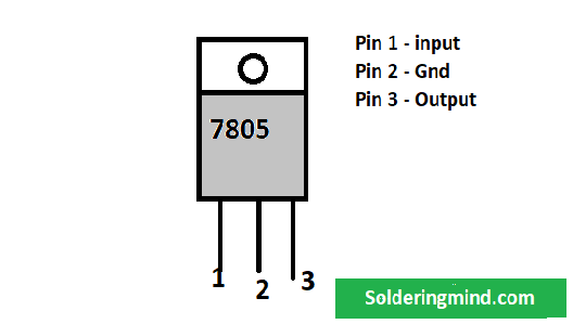
LM7805 Pinout
Connection and Working
In the first pin connect a 100 uf capacitor. And also connect 100 if to the output pin of the voltage regulator IC. There are no complex circuits to make the 5 volt supply. only a few components are used in this circuit to convert the 12 volts to 5-volt dc. (Here I am using the input voltage of 12 volts.) You can use any voltage range between 7 to 25 volt.
Features of 7805 voltage regulator IC
- 5v positive regulator
- Internal thermal overload and thermal protection system
- Input minimum voltage 7v DC
- Maximum input voltage 25 v dc
- Constant supply.
You may also check:
- 12v to 6v voltage converter circuit diagram
- Toroidal transformer winding calculation
- Transformer Winding calculations
- How to build an FM transmitter
- Sg 3525 ic inverter circuit diagram with PCB