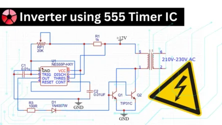
In this article i’m showing How to make inverter easily at home. The power inverter project that you can use in your home appliance easily. This circuit is based on the PWM IC of SG3525.
Requirements
To make an inverter you need main 3 setups, that are
- Battery
- Inverter driver board
- Transformer
Battery– use 12 v high power battery
50hz driver board – the inverter board will generate the pulses 0f 50hz and that will transfer to the transformer primary coil.
Transformer – use 12-0-12 10 a step up transformer
The PWM IC is most commonly used in the power-ups circuit and also in the SMPS circuits. The working voltage of this circuit is 12-volt dc and you can achieve up to 1500 words according to your Transformer and the most that you are using in the driver board.
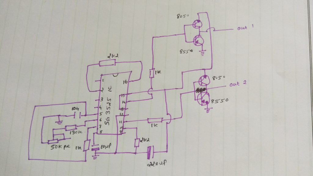
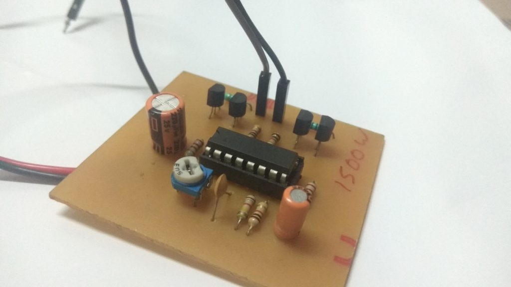
Inverter Driver Board Circuit
Components Required
- SG3525 ic ——————————–1
- 8050 transistor————————-2
- 8550 transistor————————-2
- 104 pf capacitor———————–1
- 50k pot ————————————1
- 10uf capacitor————————–1
- 220uf capacitor ————————1
- 130k resistor—————————–1
- 2k2 resistor ——————————2
- 1k resistor ——————————–3
- 12v 90 ah battery———————–1
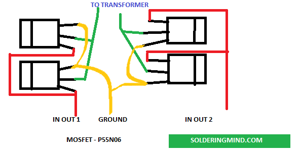
- mosfet p55n06 ————————–4
Features of SG 3525 IC
- 8.0 volt to 35-volt operation
- 5.1 volt plus or minus 1.0 % trimmed reference
- Separate oscillator sync pin
- Adjustable deadtime control
- Input under voltage Lockout system
- Shutdown input.
- Soft start
- Reference voltage input section.
Connection and working
The driver board that producing PWM signals in pin no 11 and pin number 14. the signal producing at the frequency of 50 Hz. and the frequency has to be amplified by the power MOSFETs of the P55n06 N channel. then the drain pins are connected to the transformer. when the power is on the 50hz signal that passes to the primary winding of the coil and the transformer will producing the emf Know how to works the transformer. then inducing a voltage in the secondary coil and ( step-up transformer number of the coil is high ) so we get 220v ac.

I love this project
But I want to make pure sine wave using egs002 can you help with circuit diagram abd pcb
Thanks
Iam going to make this…
great
I love this
THANK YOU
Thanks buddy
PCB banane keep lite kya lagega please bataye