The clapper light is an interesting circuit that turns on the lights when you clap your hands near the connected mic. So this circuit is known as ”The Clapper Light” But sometimes it will turn on when any sound is equal to the wavelength of a clap sound. The main circuit contains a single 555 IC and a condenser mic. The condenser mic acts as the sensor to sense the external clap sounds.
Clap Light Circuit Diagram
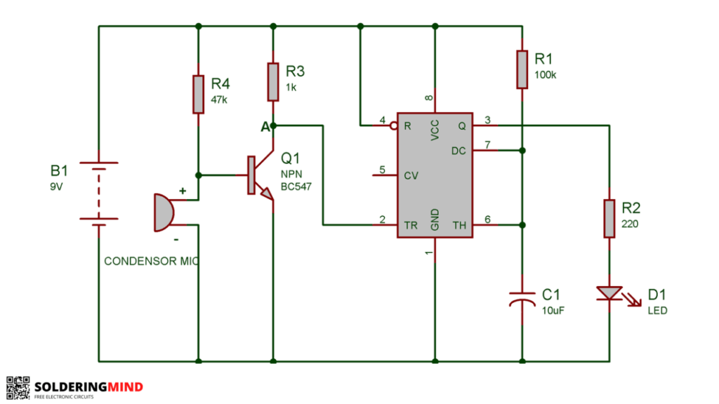
The condenser mic normally converts the sound energy into an electric energy, that will trigger the 555 IC to turn on the circuit diagram. If the 555 IC gets any triggering signal from the condenser mic then the output pin of the 555 IC gets high and turns on the light.
When any clap sound is detected by the condenser mic the IC turns on after some time the light gets turned off. The light remains on for some minutes then only it gets turned off. This circuit diagram is a very simple and sensitive one, a lot of clap switch circuits are available on in internet but the 555-based circuit is very easy to build.
How Does The Clapper Light Switch Work
When any clap sound is detected the condenser mic gets activated ( The sound energy is converted into electrical energy ) triggering electrical voltage turn on the 555 IC. The IC gets triggered to turn on the output-connected lights.
Components List
- 555 Timer IC
- Condenser Mic
- BC547 Transistor
- 220, 1k, 100k Resistors
- 10uF Capacitor
- LED Lights
- 9V Battery
- Bread Board and Wires ( optional if you are assembling on a breadboard )
You can see the complete circuit of the clapper light. The electronic components are mentioned near the corresponding component. In the initial stage, the Q1 transistor is in an OFF state, Because there is no required voltage to open the transistor.
Point A is connected to the positive voltage of the battery through a 1K resistor and it straight goes to the triggering pin of 555 IC. As we know the 555 IC PIN 2 voltage needs VCC/3. The Pin 2 is in the high potential state so the LED is OFF.
For any clap sound produced near the condenser mic, the mic converts the sound energy to electrical energy, and then the energy passes through the second pin of the condenser mic. Then a minute negative potential reaches the base pin of the BC547 transistor.
At that time the transistor turns off and it happens in milliseconds and a triggering potential difference is generated in point A. At that time 555 IC turns on and the light gets glowed.
After some time passes the connected LED lights get turned OFF automatically because the circuit diagram is designed. The 555 IC is in Monostable Mode. Led will turn on the time is determined by 1.1*R1*C1.
From the formula, we can change the turn-on duration by changing the resistor and capacitor values. We can easily redesign the circuit to integrate it with AC circuits.
To use this same circuit as an AC circuit, you need to add a relay circuit instead of the lights connected to the circuit. 12v adapter or 12 v transformer with proper AC to DC rectifier is using when you are planning to connect with AC circuits.
- From the circuit most of the viewers do not find the voltage rating of the capacitor, you can use a 16v or above voltage-rated capacitor to build this circuit.
- If you want to connect high-power-rated LED lights you need to add a relay circuit and connect the light through the relay contacts.