Here is the circuit diagram of the 12v to 6v converter power supply circuit using 7806 regulators IC. the 7806 regulator IC contains a three terminal. This positive voltage regulator that available in the TO 220 plastic package.
Circuit Diagram
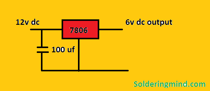
The 7806 regulator IC consists of the current limiting, thermal shutdown this makes the good output of 6v power supply. You need to place a proper heat sink because it produces some amount of heat during the working process.
LM7806 Pinout
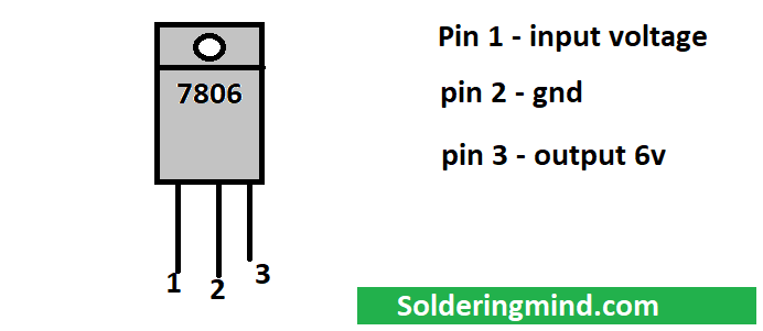
From the 78++ series of the voltage regulator, 7806 regulator IC is used to regulate the output voltage 6 volt (it’s a fixture constant value in the minimum Voltage fluctuation). The different chip manufacturing companies providing this ic with different output current and over current protection characteristics. each IC may have different output current characteristics varying from 1 ampere to 1.5 amperes.
You can increase the current from 7806 by using a power transistor. I just used a Tip 2955 transistor and the circuit can drive the output voltage 6v along with 3 amperes.
Working
The 12v dc power supply has to be connected to the regulator ic pin number 1 and a 100 uf capacitor has to be connected in the positive and negative connection, the ic convert the 12v dc supply to 6v dc supply ( constant power supply voltage.


Bro,I have electronic weighing scale company.i want 12v-40 ah dc to 7.5 v- 5 ah converter.please tell ideas.
use buck converter