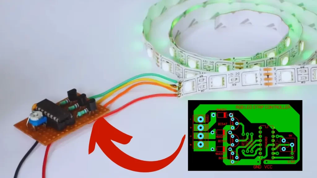
The RGB LED strip is very beautiful to see and it’s working too. The lights are Eye catching colour combination comparing to any other LED light strips. But this RGB LED Strip needs a Controller circuit.
So in this article i will show you the RGB Led strip controller circuit using a single IC of CD4060. This circuit can easily control the light speed and it will make smile in your face while its start to work.
RGB LED strip Controller Circuit Diagram
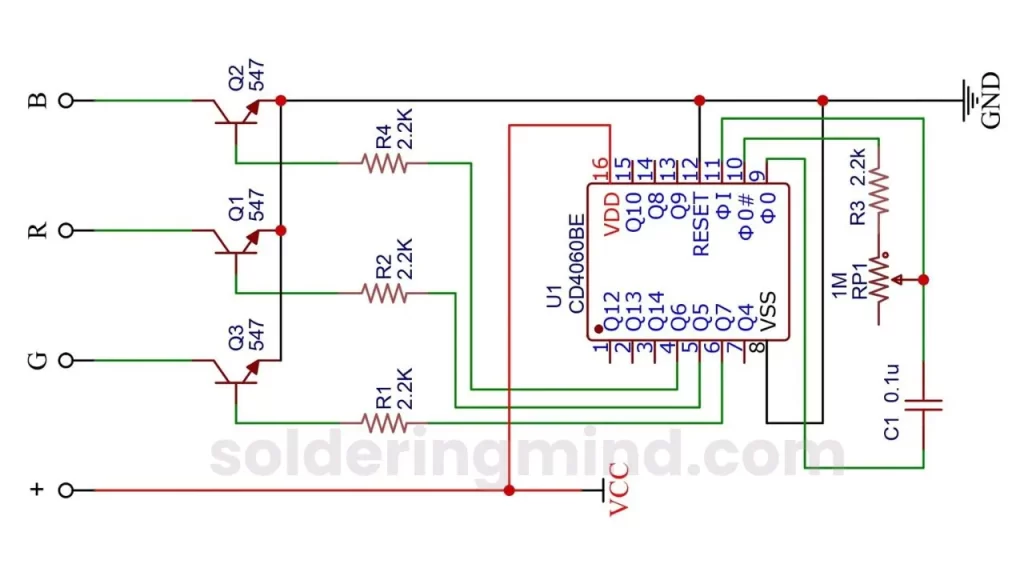
Components Required
- CD4060BE IC – 1
- 1M pot – 1
- 2.2K resistor – 4
- BC547 Transistor – 3
- 0.1uf capacitor – 1
- 12V Battery
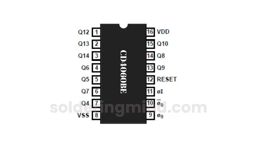
Components Pinout Diagram
CD4060 IC Pinout
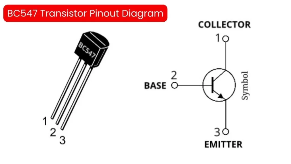
BC547 Transistor Pinout
Working
The CD4060 IC is a popular IC that is used in various applications such as timer frequency divider, and clock generator. It works as a 14 stage binary ripple counter and oscillator. Each stage will be represented as a binary bit ( Q0 to Q13 ).
The counter will start from Q0 to Q13 if any clock pulse is applied. The inbuilt oscillator of this IC provides a clock signal for the IC. The oscillator frequency is determined by the external components connected to the IC.
Changing the values of components will change the clock frequency. Also the IC provides a different division ratio that will allow you to divide the input voltage clock frequency to lower frequency.
The reset pin of the IC provides the reset function. That will start IC work from the initial state. The simple and flexible operation can be achieved with CD4060 IC.
FAQ
The CD4060 is a 14 stage binary ripple counter with built in oscillator circuit. it can able to produce selectable time delay.
The cost of a single CD4060BE IC is Around 0.85$
The in built RC oscillator frequency is about 690Khz min.
When clock pulse received the IC start to shift positive voltage from Q0 to Q13 based on the input clock speed.