Fan regulator is essential to control the speed of your ceiling fan or table fan. Sometimes the fan regulator switch will go damaged and not work. To overcome this issue, I just sharing a wonderful circuit for controlling your dealings fan speed.

Ceiling fan speed is controlled by adjusting the input voltage to the fan coil. The regulator working based on this principle, when you rotating clockwise direction the speed will be increased and visa versa.
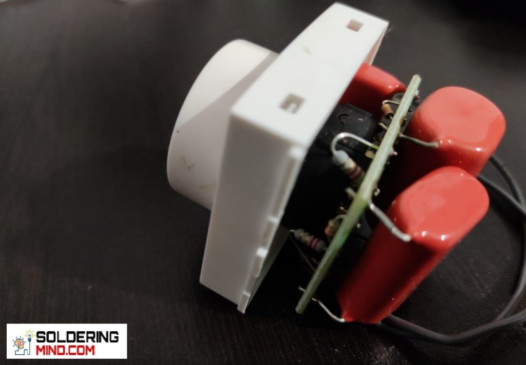
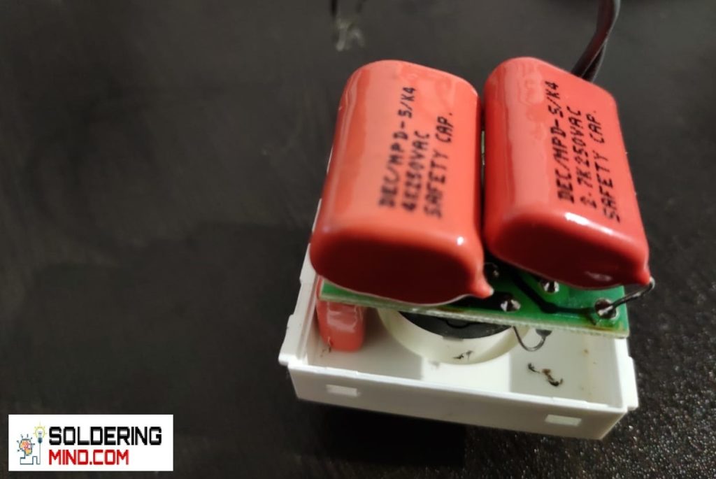
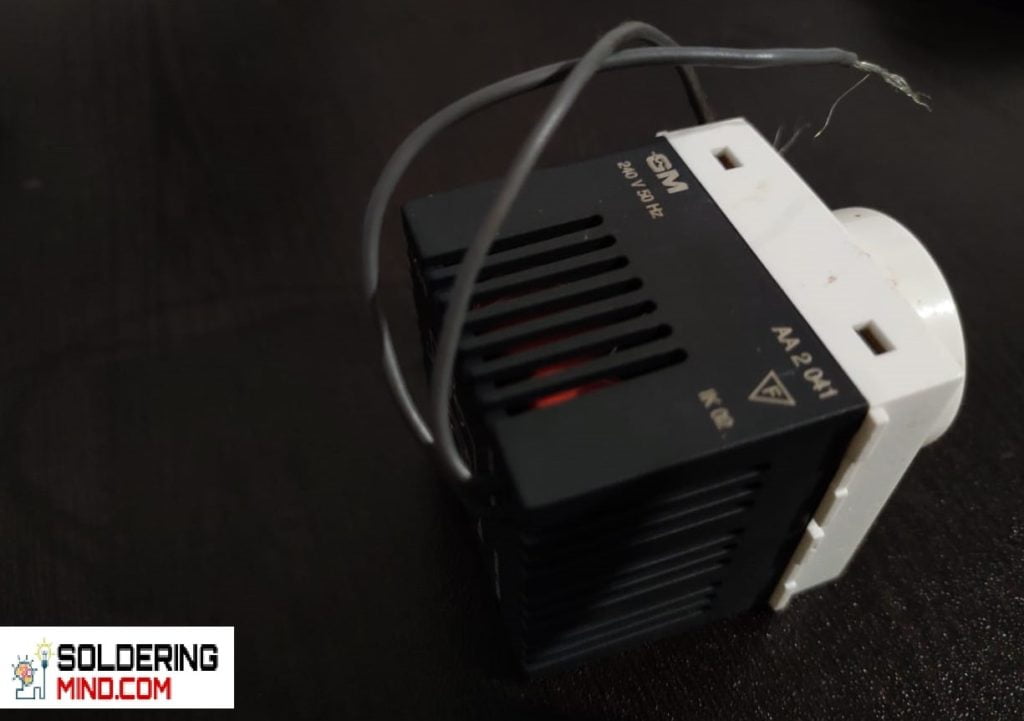
In most of the regulator are comes with a regulator knob or fan regulator switch. This fan regulator rotary switch will be composed of a capacitor and resistor. If the rotary switch gets damaged, you need to replace it it’s very difficult ( because the switch is not easily available in the market ).
Circuit Diagram
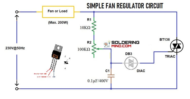
The simple homemade fan regulator working based on a triac and diac, BT136 is used in this circuit to control the ceiling fan speed. The circuit consist of minimum number of components and you can easily build.
CAUTION: The working voltage is 230 v AC. The components are contained AC voltage so dint touches any components when the circuit is connected to the mains.
Advantage of Fan Regulator Circuit
- Stepless control of speed
- Power saving and low energy consumption
- Cost effective.
Components Required
- Triac – BT136
- Diac – DB3
- Resistor – 10K
- Potentiometer – 100k
- Capacitor – 0.1uf/400v Capacitor.
- 230v – 250v AC 50 Hz
- Ceiling fan ( Below 200W)
Circuit connection
- Know about the terminals of all the components for phase and neutral connection. choose the fan or any other electric motor ( the power should be below 200 watts ).
- Take a dotted printed circuit board and place the components on the board. Connect the BT136 Triac 2 Terminal PIN 1 and PIN 2 that is represented as input and output. Connect PIN 1 to the neutral or phase, the PIN 2 taken as output which connected to the ceiling fan connection.
- connect 10K resistor and 100k Potentiometer with 0.1 uf capacitor in series.
- Connect DB3 diac in the potentiometer remaining pin and it will be connected to the Triac Gate Pin.
Working of Fan Regulator circuit
When the voltage applying to the circuit, the potentiometer adjust the voltage of the output by controlling the Triac. if the potentiometer is in high resistance the voltage in the gate is very low and triac will wont allow high voltage passage. This is the main mechanism of this circuit.
Ceiling fan regulator not working?
The ceiling fan is an electric motor that working based on the principle of electromagnetic field creates in the stationary coil. The copper coil winded is known as the stater and the field is known as the rotary.
Voltage passing through the coil will determine the speed of the rotation. if the voltage is high ( 230v AC), the fan rotates at its maximum speed. if the voltage reduces the speed also goes down. In between the ceiling fan and voltage input connection we connecting with the fan regulator.
so, it’s clear that a fan regulator is used for controlling the fan speed by adjusting the input voltage to the ceiling fan.cealing fan without regulator the fan rotates its high speed.
The main cause is damage to the rotary switch or the circuit. The inside of the fan regulator circuit consists of a capacitor. If the capacitor gets damaged or weak. The speed control can’t be work properly. For example, if you are rotating the rotary switch fan is not rotating.