
The police flashlight, also known as a tactical flashlight, is a vital tool for police officers in their line of duty. The Flashlight is in the flickering type and the color of RED & BLUE.
Do you know why they are using this flashlights? The Police flashlight is crucial one while the police officer is in duty time, the flashlight will giving more visibility in dark places or in night time.
In rescue mission or chasing the light have more important role to identify the people about the urgency and also people can easily identify the cops at any time or rush area.
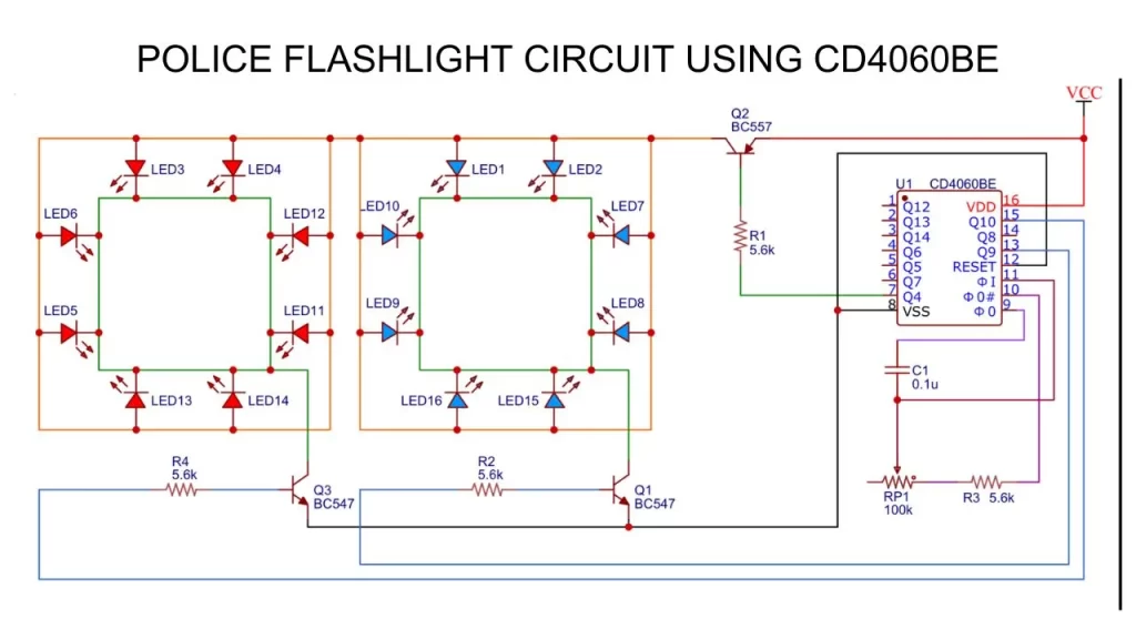
In this article i am sharing the idea about How to make a police flashlight using IC CD4060BE. The circuit diagram, Components list and Working of this circuit is explaining here.
Police Flashlight Circuit
Components Required
| Components | Quantity |
| CD4060BE IC | 1 |
| BC557 Transistor | 1 |
| BC547 Transistor | 2 |
| 100k Pot | 1 |
| 5.6K Resistor | 4 |
| Red LED | 8 |
| Blue LED | 8 |
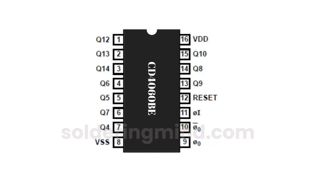
CD4060BE IC Pinout
Working
The CD4060be IC is a 14 stage ripple carrying counter IC with in built oscillator. The IC produce 12MHz oscillator frequency at 15v input. The IC also have common reset pin to reset the circuit.
The PIN number 9, 10 and 11 are responsible for the smooth working of this circuit. The frequency of the IC is determined by the external capacitor connected to the PIN number 11, The 100k pot connected to to PIN number 10. The oscillator frequency is calculated by,
F= 1/ (2.5 x R1 XC1 )
Based on this oscillation the output transistor of BC547 is switching and it makes the LED lights as a strobe like appearance. The speed of the LED flashlight can be controlled by rotating the 100K Potentiometer.
How to Build
Time needed: 1 hour
The brief explanation of how to make a police flashlight circuit diagram on a zero PCB or dotted PCB.
- Gather all components
First you need to gather all the required components for this project. The components are properly check and confirm that all are working fine without any issues.
- Placing Components
You need to place the Components on the breadboard or zero PCB. Solder the components or do the connections properly as per the circuit diagram given in the above figure 2.
- Do proper Checking’s
Do proper checking of the connections before power on the circuit. Any improper connections or missing connections will damage the circuits or not work.
- Powering the circuit
Provide the power supply by attaching the positive terminal of the battery to the positive supply and negative to the battery negative.
- Adjust the speed or strobe flashing
After turning on the circuit the led get start to flash. You need to adjust the light flashing pattern by rotating the 100K pot.
FAQ
Producing different output at fixed interval of time it is based on the oscillator frequency of the inbuilt circuit and external components.
You can use the CD4024b ic it is a 7 bit and 12 bit binary counter IC.
The binary counters are the binary sequence generators. They produce the binary sequence in output based on the input clock signals giving as the input to it.

I love seeing discoveries and learning new things and it’s great to keep innovating, thank you very much