In this article, you will get a clear idea about Arduino nano pinout, Board diagrams and its connection details. for better understanding schematic representation also included.
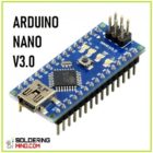
Nowadays technology developing very fast. The transistor and integrated based circuits are changed to the latest analog and digital technology. The programmed microcontroller is available to do all the functions. The Arduino nano is one of them, Arduino nano working with the support of a tiny microcontroller of ATMEGA328P.
You can able to write the code and programming through your computer or cell phone ( android Arduino app). A little knowledge is enough for small projects and a high level of robotic projects can also be developed using this tiny chip.
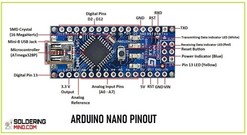
Arduino Nano Pinout
| PIN NUMBER | PIN NAME | PIN FUNCTION |
| 1 | D1-TX | Digital I/O pin Serial Tx pin |
| 2 | D0-Rx | Digital I/O pin Serial Rx pin |
| 3 | RESET | Reset connection |
| 4 | GND | Ground pin |
| 5 | D2 | Digital input or output pin |
| 6 | D3 | Digital input or output pin |
| 7 | D4 | Digital input or output pin |
| 8 | D5 | Digital input or output pin |
| 9 | D6 | Digital input or output pin |
| 10 | D7 | Digital input or output pin |
| 11 | D8 | Digital input or output pin |
| 12 | D9 | Digital input or output pin |
| 13 | D10 | Digital input or output pin |
| 14 | D11 | Digital input or output pin |
| 15 | D12 | Digital input or output pin |
| 16 | D13 | Digital input or output pin |
| 17 | 3V3 | 3.3v output voltage |
| 18 | AREF | Analogue reference pin |
| 19 | A0 | Analogue input pin 0 |
| 20 | A1 | Analogue input pin 1 |
| 21 | A2 | Analogue input pin 2 |
| 22 | A3 | Analogue input pin 3 |
| 23 | A4 | Analogue input pin 4 |
| 24 | A5 | Analogue input pin 5 |
| 25 | A6 | Analogue input pin 6 |
| 26 | A7 | Analogue input pin 7 |
| 27 | 5V | 5v input or output |
| 28 | RESET | resent connection pin |
| 29 | GND | ground |
| 30 | VIN | voltage supply input |
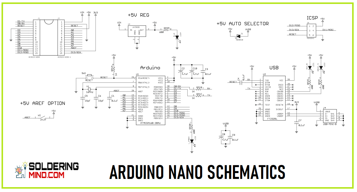
Arduino Nano Schematics
Arduino nano pin configuration
| PIN CATEGORY | PIN NAME | DETAILS OF EACH PIN |
| Power | 3.3v,Vin,5V,Gnd | Vin- The pin provides the input voltage to the Arduino when the time of using an external power source. 5V- This is the regulated or fixed voltage used to power the microcontroller and other components. 3.3v- is generated by the board voltage regulator with a very small current. GND- represented as the ground or negative supply. |
| Reset | RST | To resetting the micro controller. |
| Analogue pins | A0,A1,A2,A3,A4,A5,A6,A7 | Using for analogue voltage inputs. the maximum input voltage is 5v. |
| Digital pins | D0 to D13 | These pins can be used as an input or output. the low input voltage is 0v and high at 5v. |
| Serial communication pins | Rx,Tx | Using for receive and sending serial data. |
| PWM | 3,5,6,9,11 | Provides the PWM outputs. |
| External interrupts | 2 and 3 | Used for triggering an interrupt. |
| Icsp | 10,11,12,and 13 | Used for the SPI communication. |
| AREF | AREF | Reference voltage input or output. |
| LED | 13 | Inbuilt Led |
ICSP pins
| ARDUINO NANO ICSP PIN | PIN FUNCTION |
| GND | Supply ground |
| RST | Reset connection input |
| MOSI | Master output slave in |
| SCK | Clock from master to the slave |
| VCC | Voltage input |
| MISO | Master in slave output pin |
Digital pins
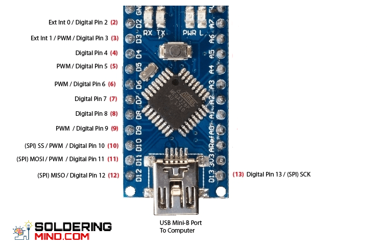
The Arduino Nano has 14 numbers of digital input or output pins. The pins working at the maximum input voltage of 5v. If the digital is low the output voltage is 0v, and the digital pin is high the voltage is about 5v.
Serial communication pins in arduino nano
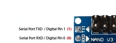
Serial communication pins are PIN 1 and PIN 2. Pin 1 is RX and Pin 2 is TX. These pins are transmitting and receiving the communication signals.
PWM pins
Already mentioned above, these digital pins provides the PWM output signals.
spi pinout
These pins support the synchronous communication with SCK. act as a synchronizing clock.
Arduino nano analog pins
The analogue pins are starts from PIN number 1,2,5,6,7,8,9,10,11,12,13,14, and PIN number 16. These 14 analogue input or output pins works with maximum voltage of 5v.
AREF pin arduino
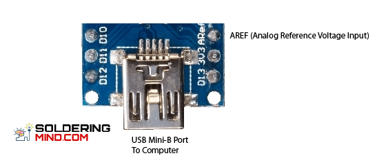
AREF stands for Analogue Reference. This is the feeding input for the Arduino. The reference voltage is connecting through this pin. AREF having the input resistance of 32k. If you are going to feed the reference voltage you needs to call the analogue reference before call to analogue read.
AnalogueReference(EXTERNAL) ; analogue read (0) ;
If you didn’t do this on your program the microcontroller get short internally with the 5 V. Otherwise the IC will burn out.
Reset Pin
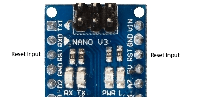
Reset pin is doing the job of totally reseting the microcontroller ( atmega328p). Which means the program will be restored or restarted as like the initial uploaded state. Most commonly the reset can done though a switch connected to the 27 th pin of Arduino. If the 27 th pin is Low or 0 volt, the IC get restarted.
ICSP ( In circuit serial programming)
The icsp pin is stands for in circuit serial programming. Is a AVRtiny programming header in the arduino board. It consists of the pinout of MOSI,MISO,SCK,RESET,VCC,GND. This pins are useful for programming Arduino board in the situation of error in bootloader. To reprogramming the bootloader connecting this pins to another Arduino board with same icsp pinout. For example Mosi pin connected to the Mosi pin of second Arduino board and sck to sck pin.
Power
The working voltage of Arduino nano is 5v and powerd through the mini B Usb. A 6-20v unregulated power can be applied through pin number 30. And a regulated 5v can apply through pin number 27.
Difference between arduino uno and arduino nano
| SPECS | ARDUINO UNO | ARDUINO NANO |
| Input voltage | 5v/6-12v | 5v/6-12v |
| Processor | Atmega328p | Atmega328p |
| Analogue I/O | 6/0 | 8/0 |
| CPU speed | 16MHz | 16MHz |
| Digital I/O/PWM | 14/6 | 14/6 |
| EEPR/SRAM | 1/2 | 1/2 |
| Flash | 32 | 32 |
| Usb | Regular | regular |