You are worried about the calculation of the value of the inductor. The only easiest method is to use an inductance meter. The inductance meter or LC meter does not get through at a cheap rate. The cost of this product is around 10 to 15$.
So, for this reason, beginners in electronics can not buy this one. But most of the inverters, converters, booster circuits, and Class D amplifier needs the inductor.
I just made a class d amplifier but I can not know if the inductor is in the 22uh range or not. I don’t know for that reason my amplifier project is pending. Too much tension and sadness happen to me. At that time I planned to make an inductance meter it’s necessary for me. I think all electronic hobbyists should have this inductance meter. This will help in doing several electronics projects.
These days several free circuits are available for making inductance meters. But they are very difficult to code. Ex PIC 16 series IC. But in those circuits, the clear code is not available and can’t be trusted. So I decided to make an inductance meter using Arduino Uno ( IC Atmega328p ). Arduino is very cheap and the IC rate is about 120 rupees or 2$. Yes great with a cheap rate we can build an inductance calculating meter.
I designed a code for an inductance meter using Arduino programming software. At the last of this article, I pasted my working code of the Inductance meter. This code will help you when you want.
How to measure inductance
Mehandi the inductance is defined as the ability of the coil to restrict the passage of current through it. The inductance can be measured in Milli Henry or microhenry. The inductance can be measured using a frequency generator or using an oscilloscope.
To find out the inductance the basic formula is described as the bacterium depending on the inductance x the rate of change in current.
The inductor in parallel with the capacitor is called an LC circuit. When we measure the inductance the added inductor changes the oscillator frequency and calculating the change in frequency we will analyze the exact inductance of the inductor. The microcontroller purchases Atmega 328 p analyzing analog signals. The mega 328 p can be sampling the analog signal at 9600hz. The ship is specially designed for converting the analog signal to digital signals
LM 393 IC is a comparator that switches the signals faster than LM 741 IC. The voltage difference in the LC circuit becomes positive then the LM 393 IC starts to float and gives a pull-up through the resistor. When the voltage difference in the LC circuit becomes negative then it will pull up to the ground.

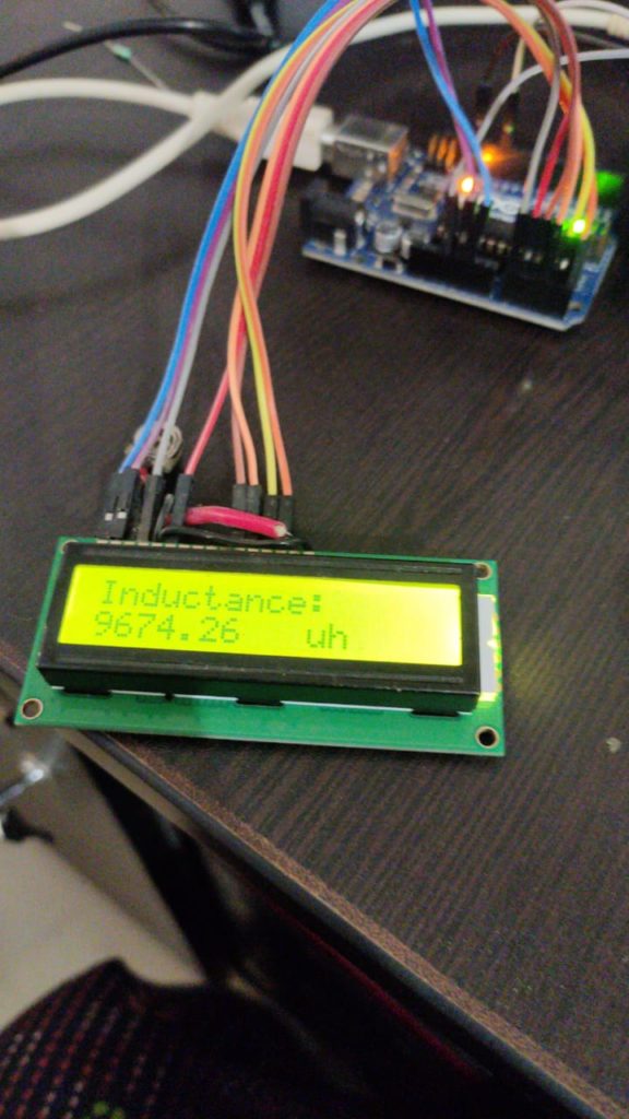
In this circuit, we are applying a frequency to the LC circuit. It is about five volts compared with the IC of ATMega 328. After that, the resonating frequency can be calculated by using the formula and displayed using 16 cross 2 LCD.
Inductance measuring calculations
F=1/2*pi*(LC)^0.5
and from this equation, we can find out the frequency of the LC circuit.
From the above equation the resonating frequency will be calculated and changing with this equation will give the inductance of the inductor.
L= 1/4*pi^2*f^2c. f is the resonating frequency. C is the capacitance and L is the inductance.
Components required
- Atmega328p
- Arduino Uno
- Bootloader circuit
- 16*2 LCD display
- 10k pot
- 22pf capacitor
- 16mhz crystal
- 560R resistor
- 1N4007 diode
- 150R resistor
- 330 R resistor
- 1uf capacitor
- 7805 regulator IC
- 1k resistor
- LED
- PCB copper clad
- Ferric chloride
- Connecting wire
- Jumper wires
16*2 Display connection

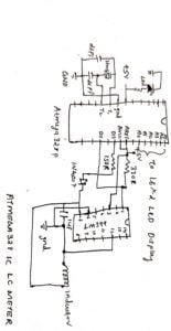
As per the circuit diagram of the 60 *2 LCD display. Connect the first pin of the LCD display to the ground. The second pin is connected to the positive voltage supply of 5 volts. 53 is the brightness adjust which will be connected along with the 10k pot.
Rs,e, Db4, Db5, Db6, and Db7 connected to the Arduino pin for mega 328 IC pin A5, A4, A3, A2, A1, A0.
Circuit Diagram

Did any one succeed on building this inductance meter?
Their is no doubt about this project already checked and working one
salam
Hi
sent cod arduino pls
Dear, please could you send me the source code and schematic? i’m building this but it’s not working. Thanks
[email protected]
sent cod arduino pls
[email protected]