Let’s build a simple 300w power inverter using TL494 with a feedback system. This inverter works based on a high frequency; its operating frequency is around 30-50khz. The normal 50hz transformer can not handle this frequency, so we need a Ferrite core transformer. the EI33 or EE35 ferrite core transformer is the best choice.
300 watts Inverter PCB layout
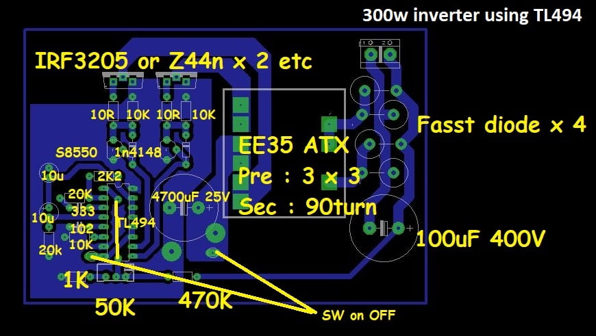
The inverter works based on the switching IC of TL494. The IC generates high-frequency pulses (about 30khz). The pulses are amplified by the MOSFET of IRF3205 and pass through the transformer. The Fast diodes are rectified and give the power output.
TL494 ic pinout

List of components
- EE35 transformer – 1
- TL494 ic – 1
- IRF3205 – 2
- 4700uf/25v – 1
- 1000uf/400v – 1
- fast diode – 4
- 8550 transistor – 2
- 4148 diode – 2
- 50k preset pot – 1
- 10R resistor – 2
- 10K resistor- 3
- 20k resistor -2
- 2.2k resistor – 1
- 1k resistor – 1
- 333 pf capacitor – 1
- 102pf capacitor – 1
- 470k resistor – 1
- 10uf/25v capacitor – 2
Transformer winding
Take EI33 or EE35 high-frequency transformer (ferrite core) The primary winding should be 3+3 turns with 18 swg copper wire or 3 combined 22swg wires. Secondary turns with 22swg wire of 90 turns.
Input voltage
Use 12 volt 20A battery to get 300watts output,
Adjust the preset to set the output voltage to 240 voltage by measuring with a voltmeter.

Use IRF3205 or IRFZ44. I recommend using IRF3205 because of its high power handling capacity. Compared with the two MOSFETs, the IRF3205 is the best choice. Use a proper heat sink for heat dissipation. Large heatsinks will reduce overheating issues. Use thermal pastes to protect each MOSFET from a short circuit. if you have any doubts about this article just comment here I will resolve the issues as soon as possible.

Thank
You are welcome
Can we use the same feedback preset 50k to set the put for higher voltage like 300 Volt?
“use thermal past for protecting each MOSFET from a short circuit”……
Dear Sir, thermal paste is NOT used for preventing short circuit, it is used for better heat conduction from the device to the heat sink.
You have not provided any circuit diagram for this project, so it is as good as useless for us.
Please l need the schematic diagram of the 300 Watt inverter circuit. Thanks
I love your videos on YouTube