How to convert a high voltage DC supply to 240 v AC. I hope you have a better idea about these DC and AC voltages.
Introduction
Ac the alternative current that the phases are continuously changing as per the frequency. The normal home appliances are working within the voltage range of 220-250v AC voltage at 50Hz frequency. So the concept is clear.
Dc is the direct current, it is a linear voltage without any phase changes. So it has a fixed positive and negative terminal. From this, you will get a better idea about the DC voltage and AC voltage.
But in this article, we deeply discussed with the conversion of a high volt DC supply to an AC supply. For this, we need an electronic circuit board called an inverter. Mostly the inverter works with a 12 v battery or 48 v DC source.
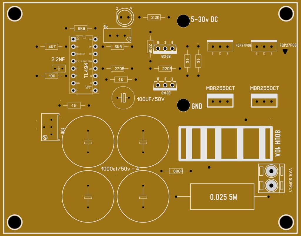
The parallel connection will provide a huge voltage range as you want. But it is foolish thinking because if you need 120 v dc you need to connect about 10 batteries with a 12 v rating. It is impossible. For these conditions, we are using an Smps circuit to convert 12 v DC to 300 v DC.
In this way, we can easily obtain the higher voltage. So using this converter will reduce the number of batteries.
Also check, 500w 12v to 300v dc converter circuit project
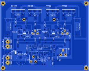
300 v Dc to 220v AC Converter
Working
The circuit is working based on the PWM ic sg3525 and an H bridge circuit. The PWM will provide 50hz frequency so the working with that frequency as the same to the alternating current. So the H bridge MOSFET receiving the high voltage DC to it. Then the voltage is from any switched-mode power supply or high-frequency inverter. The voltage will be in the high frequency and it’s about 50-60khz frequency.
Then the high-frequency DC voltage will be converted into low-frequency AC voltage. it is suitable for a working fan, mixer grinder, and other home appliances. Using a few components you will get the power supply board easily.
Let’s discuss 300 v direct current to 220 volt AC converter PCB. The main part of this PCB is SG 3525 IC. It’s a normal PWM IC that is mostly used in the inverter circuit. Bhai using this IC we will generate the output pulse with 50 Hertz.
This oscillator frequency will drive the four MOSFETs of IRF460. In SG 3525 the frequency is determined by the resistor and the capacitor connected in the PIN number 5 6 and 7. PIN number 5 and 6 are the important components for generating the determined frequency range. In this circuit year using 104 PF capacitor in 5 the pin of the IC. And using a 130 k resistor in VI. These two components will generate a frequency output ranging from 50 hertz to 60 Hertz. The DC input of 300 will be injected into these four MOSFETs. This higher DC voltage will be converted into AC voltage.
A 12-volt dc supply is provided for working this circuit. I am already giving the SMPS circuit for converting a 12-volt DC supply to a 300-volt dc supply by using an Atex transformer.
A special feature is also embedded in the circuit board you can also see that a 10k port will attach along the IC. this sport will determine when the IC will send off I already said this for below 10.5-volt DC the circuit will automatically shut down.
Download PCB Layout
Download the PCB layout from here

I look 2 capacitor in The bord no number which number can I used go work nomaly
Pcb ka price kya hai
ye pcb mujhe bhi Chahiye
Hi Sir, Under voltage is not working as you also aware and not used 10k variable register, if you have got any solution pls share the same.
Hi Sir, can I purchase this ready made board from you.
Sir, For how much watt we can consider this circuit.
Hi sir, ac1 & ac2 points directly gives 230v AC or step up transformer is required. And why 12v dc and 300v dc wires joined with each other and after joining where these wires connected.
No transformer required
Hi sir, wiring with transformer is confusing, also if you can explain in place of music will be helpfull
You need to provide 300v dc in the 2 pin of the board and you will get the ac voltage from AC1 and AC2 pins
sir I want to purchase Dc 230 volt to 230 volt 4000 watt AC pure sine wave board please provide it to me
Hi sir, I connected 150uf,450v capacitor at rectifier diode at 300v dc, but primary mosfet burned, can we supply directly 300v dc output without 150uf, 450v capacitor.
Check proper dc is fed into the circuit
can u please tell me the width , legnth and thickness of the circuit board
Hi,How much is the maximum output power?
Based on the power stage
Hi. is this generate squrewave or sine wave.thanks
squrewave
Hi sir, wiring with transformer is confusing, also if you can explain in place of music will be helpfull
Sir can you send me the 16f72 hex file and circuit board pictures for 300 to 450 volt dc to 220 volt ac 5 kw sine wave inverter. Please
So So interesting, thanks so much Sir
Great thanks for the comments
What is the value of resistance J please?
All values are mentioned in the circuit diagram. Please check it
0R
Use jumper
circuit
47uf /63v
Yes
you show the video but you did not gave all component value
Please provide circuit diagram of 300V DC TO 220V AC and want transformer of 500w inverter
Please provide circuit diagram of 300V DC TO 220V AC
Thanks for sharing such a useful project. Sir kindly tell me about J at source pins of mosfets
you are welcome
Thank you sir, I am getting some knowledge from it.
You are welcome my friend
Good work
Sir please tell me the capacitor vellore who have with 8050 transistor
Share layout please
Givve
What cap is in between s8050 npn
Please can we have the pcb layout ?
Please provide inverter circuit too with PCB layout