In this article i’m going to share a simple amplifier circuit using LM386 op amp IC. The circuit is build with a few number of components, you can easily assemble a super amplifier using the small 8 pin IC of LM386.
Circuit Diagram
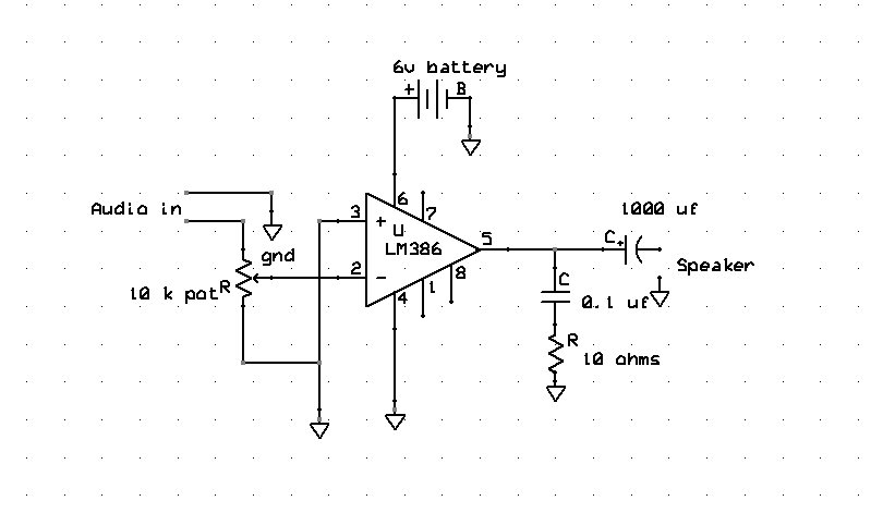
The circuit consists of 1 electrolytic capacitor and a ceramic capacitor, resistor and one 10k pot. The main component is the operational amplifier IC. The 10k potentiometer that adjusts the input audio signals and that has to be directly connected to the pin number 3 of the IC.
The battery connected in the PIN number 6 and the negative connection on the PIN number 4. The output will be taking from the PIN number 5 of the IC. we need to place A 1000uf capacitor in between the connections of the speaker to protect the IC.
LM386 Pin Configuration
The IC LM386 is a low power audio amplifier, that utilizes low power supply in electrical and electronic circuits. The IC is available in the package of 8 pin DIP.
| PIN NUMBER | DESCRIPTION |
| 1 | Inverting pin connecting the IC to the external component. |
| 2 | is the positive in that’s non-inverting pin is used to provide the audio signal into the IC. |
| 3 | is the inverting terminal and is normally connected to the ground connection of the supply. |
| 4 | is the ground pin connecting to the negative terminal of the battery. |
| 5 | this pin used to provide amplifier on how to put and allied to the speaker. |
| 6 | is connected to the power that means a positive voltage. |
| 7 | the bypass connection is used to connecting the decoupling capacitor. |
| 8 | is the gain setup pin |
Features of LM386
- The IC obtained in the package of 8 pins with DIP.
- The exterior components are minimum.
- low working voltage.
Applications
The LM386 IC used for:
Bridge oscillator, power converters, ultrasonic drivers comma TV sound system, FM radio amplifier, preamplifier, audio boosters.
How to control the gain of LM386 IC
To make the LM 386 IC to the more versatile amplifier. Pin number 1 and pin number 8 are provided for controlling the gain of the IC. A capacitor is put from the number 1-8 bypassing the 1.35 kilowatts resistor the gain will be 46 dB.
The resistor is placed in the series with the capacitor, the gain can be set in the value in between 20 to 200. You choose the external circuit as your your comfort. Download circuit diagram