The Single 74HC393 IC can able to produce dual functions because of the dual ripple counter on it. So in this article you can get the circuit diagram of binary counter with LED sequence.
Introduction
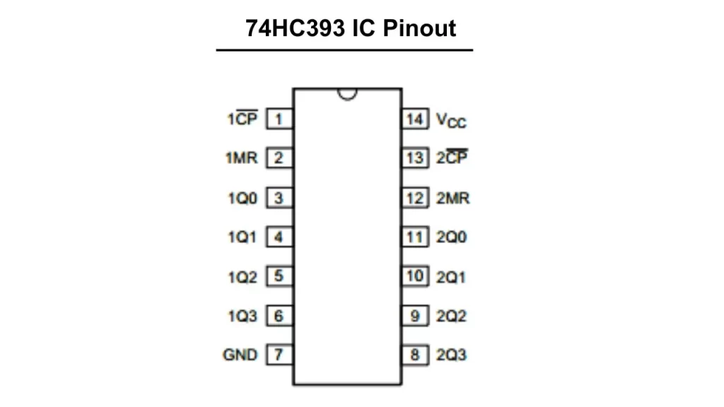
The 74HC393 and 74HCT393 is a dual four stage binary ripple counter IC. The single ripple counter contains the clock input, master reset input and buffered parallel output of Q0 to Q3. The maximum supply voltage to this IC is 6V DC so you need to add a current limiting resistor to avoid over current usage of this IC.
Because of the 4 bit ripple binary counter it is able to count up to 15 ( 1111 in binary ) before resetting the value to zero. The IC is mainly used in the applications of frequency division, time delay generation, and also the event sequencing.
The two independent counters labeled as A and B. Each ripple counter has individual flip flops. The counter A has its own clock pin and clear inputs as pin 1 and pin 2. The Counter B clock pin is 13 and clear inputs as 12 the pin. The output of the counter A is QA0 to QA3 and the counter B outputs are QB0 to QB3. When the clear inputs are high the counter will work normally.
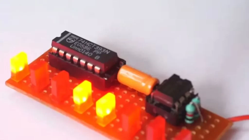
74HC393 LED Circuit

Components Required
| Components | Quantity |
| 74HC393D Binary counter IC | 1 |
| NE555 TIMER IC | 1 |
| LED | 8 |
| 5.6K RESISTOR | 2 |
| 4.7UF/16V CAPACITOR | 1 |
| 5V POWER SUPPLY | 1 |
| Connecting wires | – |
74HC393 Pinout
FAQ
Contain two flip flop counter sections. That works separately depending on the clock input. Four output is getting from the single binary ripple counter.
Two individual ripple counter is there. It is a 4 bit ripple counter.