The clap switch circuit working based on two IC of NE555 timer IC and CD4017. Both are inter connected with few components for improving the working efficiency. You can use this clap switch circuit as automatic light on/off device in your personal room, or office. Without doing any contact with the switch you can control the light or fan.
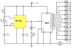
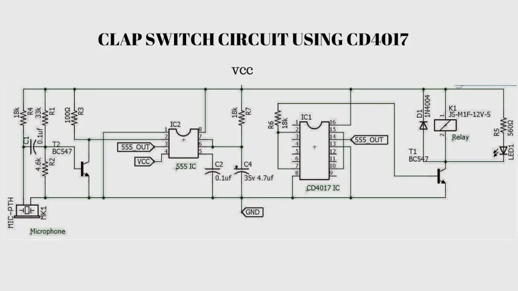
Clap Switch Circuit diagram
Components Required
| Component Name | quantity |
| CD4017 IC | 1 |
| NE555 timer IC | 1 |
| MIC | 1 |
| 12v relay | 1 |
| 18k resistor | 3 |
| 33k Resistor | 1 |
| 4.6kresistor | 1 |
| 100 ohms | 1 |
| 0.1uf capacitor | 2 |
| 560 ohms resistor | 1 |
| BC547 Transistor | 2 |
| 4.7uf/35v capacitor | 1 |
| 1N4007 diode | 1 |
How does a clap switch works?
- when any clap sound is detected by the mic it start to generate a signal.
- The condenser mike start to convert the sound energy in to the audio signals.
- The signal fed into the BC547 transistor and it boost the audio signals then goes to the 555 time ic pin 2.
- The Timer IC produce a clock signal to turn on and off the CD 4017 IC.
- when any signals reciving from the 555 ic the CD4017 ic get start to turn on or off the relay.
- At the same time the relay attached electrical equipment like lights or fan will be automatically turn on or off.
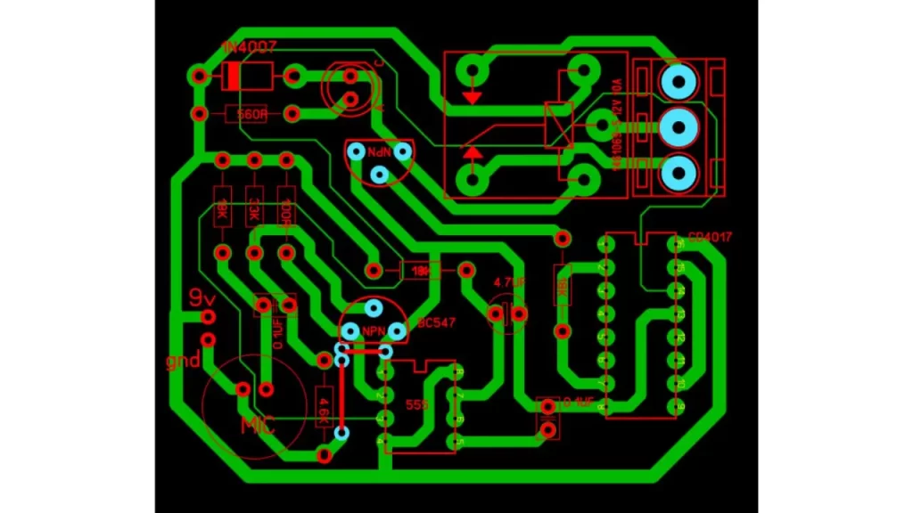
Clap switch PCB Layout
FAQ
Which sensor is used in clap switch?
The clap switch needs only the microphone (MIC) to detect the sound. no special sensor needed.
What is the frequency of clap switch?
Clap switch working based on clap sound so the frequency between 2200 to 2800 hz
What is the disadvantage of clap switch?
Anybody can turn on the connected appliances using clap sound
why we use clap switch circuit
Using to turn on any electrical equipment using clap sound.