The ultrasonic sensor will works without using any programmable IC like Arduino uno or PIC IC.The 555 Timer IC can easily operate the Ultrasonic sensor. The circuit diagram and components details are given below. you can use this circuit to build your own ultrasonic sensor circuit at home. Few components are minimal circuit diagram is great opportunity to build this circuit anyone who interested in hobby electronics.
Ultrasonic Sensor With 555 Timer Ic Circuit Diagram
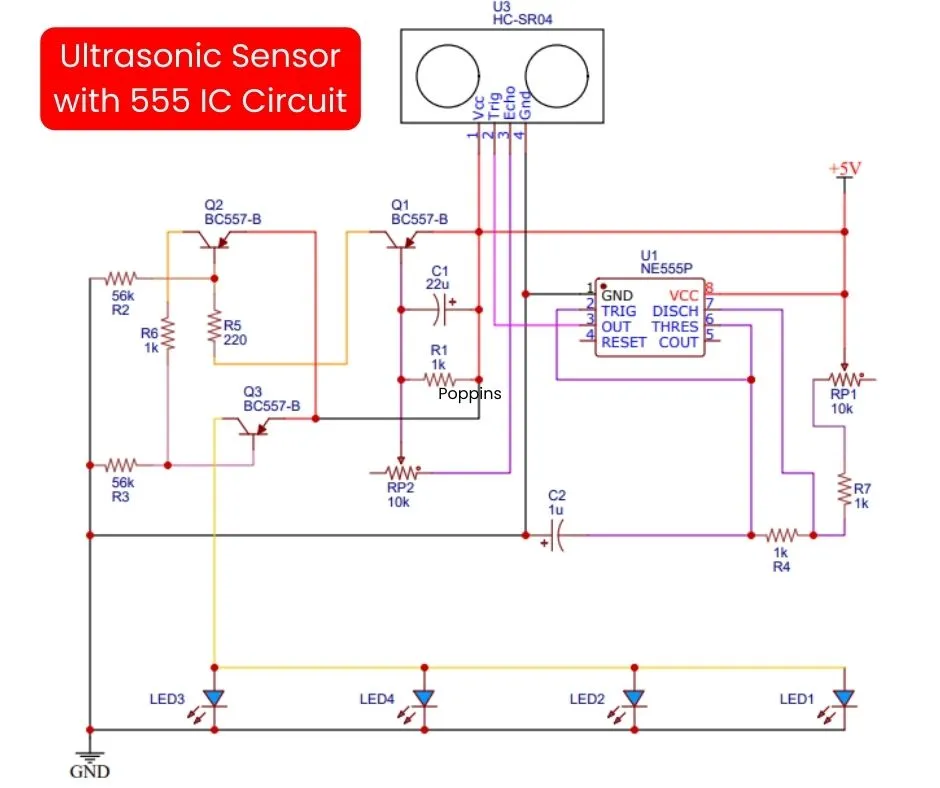
Components Required
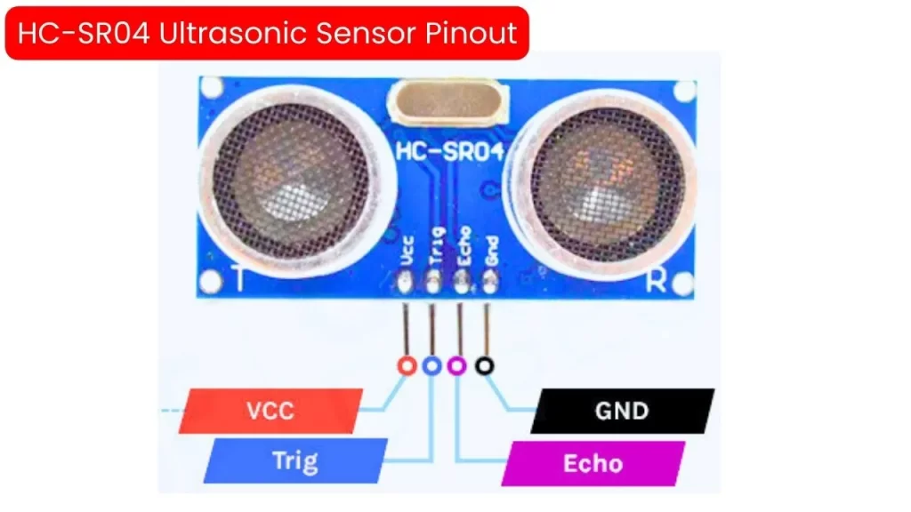
- HC-SR04 ultrasonic sensor – 1
- NE555 IC – 1
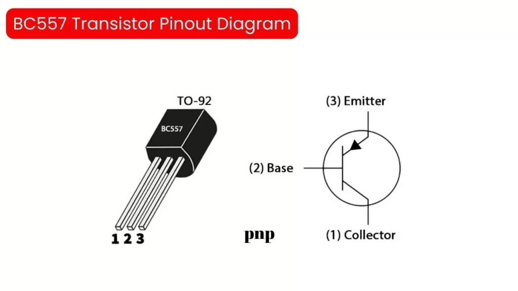
- BC 557 Transistor – 3
- 10K pot -2
- LED – 4
- 56K resistor – 2
- 1k resistor – 4
- 220 ohms resistor – 1
Components pinout diagram
HC-SR04 Ultrasonic Sensor Pinout Diagram
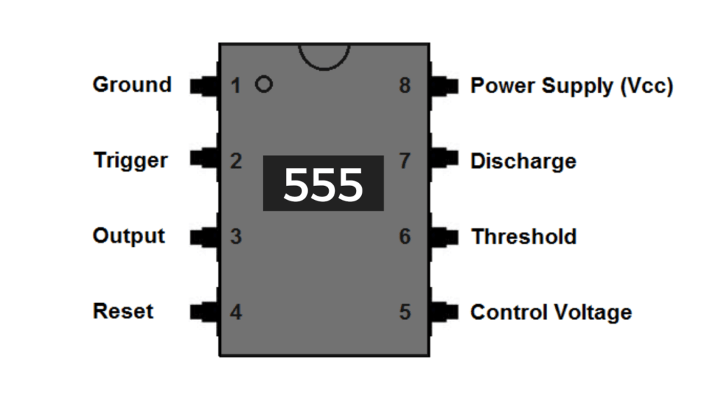
NE555 Timer IC pinout Diagram
BC557 PNP Transistor Pinout Diagram