Controlling the speed of a 12V DC motor is one of the most common requirements in electronics and students electronics projects and other automation projects. A simple and more suitable way to achieve this by using a PWM signal based technique to control speed. This article explains how to design a 12V DC motor speed controller circuit using the NE555 timer IC.
Circuit Overview
In this circuit, the NE555 timer IC is configured in astable multivibrator mode to generate a PWM signal. The duty cycle of this PWM signals is determines how long the motor receives power in each cycle, thereby this will controlling its speed of rotation. When the PWM duty cycle is increased, the motor receives more power and runs faster. when the duty cycle is reduced, the motor gets slows down and running slowly.
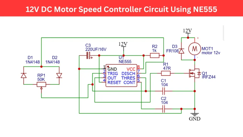
DC Motor Speed Controller 12V Circuit Diagram
Components Required
| Component | Value / Type |
|---|---|
| IC | NE555 |
| Q1 | IRFZ44 |
| D1, D2 | 1N4148 |
| D3 | FR108 |
| RP1 | 50K Potentiometer |
| R1 | 47Ω |
| R2 | 1kΩ |
| C1, C2 | 0.1µF (104) |
| C3 | 220µF/16V |
| Motor | 12V DC |
| Supply | 12V DC |
Working Principle
The NE555 timer IC produces a continuous square wave output at pin number 3. The duty cycle of this waveform is adjusted by the potentiometer (RP1) along with the connected diodes of two 1N4148.When the potentiometer is adjusted, it changes the charge and discharge time of capacitor C1.
This results in variation of the signal high (ON) and signal low (OFF) time of the output pulse, this will also varying the PWM signal at the output.
The output from pin 3 of the NE555 is connected to the gate of the IRFZ44 MOSFET. The MOSFET is acts like a high speed switch and that controls the current flow through the motor.
A wider pulse which means higher duty cycle is allow more current passing through the 12V DC motor, which makes the motor to run in higher speed. A narrower pulse or a lower duty cycle will reduces current flow through the motor and it rotates at lower speed.
The FR108 diode is placed across the motor to protect the MOSFET from back electromotive force (EMF), which is generated when the motor magnetic field is collapses.
Advantages of Using NE555 PWM Controller
- High efficiency
- Smooth speed control
- Protection from back EMF
- Low cost and easy to build
Applications
- DC fan or pump speed control
- Light dimmers (with modification)
- RC car motor control
- Robotics and automation systems
- Small-scale electric vehicles