The Light Dependent Resistors (LDR) are commonly used in automatic light control circuits and devices, where they sensing the light falling surface light level and trigger a corresponding output based on change in internal resistance . In this project, we use two LDR sensors to build a relay ON/OFF circuit and that can automatically switch load using connected relay based on light intensity at two different points.
Components Required
NE555 Timer IC
2 × Variable Resistors (22kΩ, RP1 and RP2)
2 × LDRs (Light Dependent Resistors)
2 × Resistors (10kΩ, R1 and R2)
1 × Resistor (330Ω, R3)
5V Relay
NPN Transistor (2N3904 or BC547)
Power Supply (6V DC)
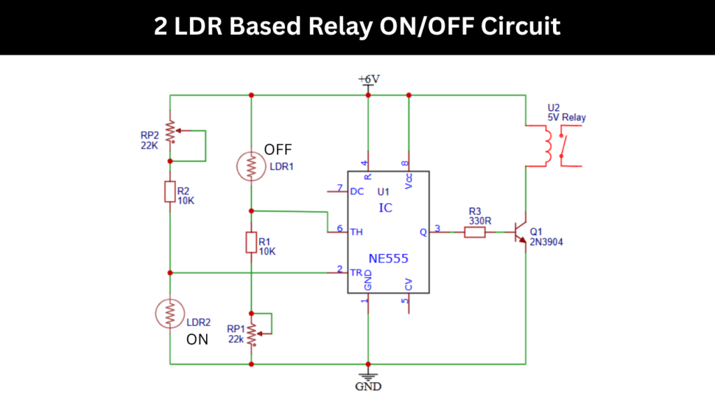
Two LDR Based Relay ON/OFF Circuit Diagram
Circuit Description
The heart of this circuit is the NE555 timer IC, which is configured in a comparator mode. It uses two LDRs. One for detecting “light ON” conditions and another for “light OFF” conditions.
Circuit Connections and Description
The LDR is connected in pin number 6 and pin number 2 of the NE555 timer IC. This two LDR is uses for different operations based on light falling on it. The LDR connected in Pin number 6 is act as a off function and the other one is for ON.
When the light is falling on the LDR1 will send signal to the pin number 6, so this will turn off the connected relay and the same LDR2 is doing when light fall on it the relay turn ON.
You can easily adjust the sensitivity of the LDR1 and LDR2 by adjusting the 22K potentiometer connected in the circuit. A 220ohms and 2N3904 NPN transistor is using in the output section to turn ON and OFF the connected 5V relay.
Check More Projects: 555 IC Projects