To Controlling the brightness of LEDs you need PWM signal based technique. So this simple LED dimmer circuit uses an NE555 timer IC configured in astable mode and a BD139 transistor is used to adjust LED brightness by varying the duty cycle of the PWM signal.
Components Required
- U1: NE555 Timer IC
- Q1: BD139 NPN Transistor
- R1: 1 kΩ (1/4W) resistor
- R5: 220 Ω (1/4W) resistor
- Potentiometer: 50 kΩ
- D1, D2: 1N4007 Diodes
- C1: 100 nF capacitor
- C2: 0.1 µF capacitor
- LEDs: 12 LEDs
- Resistors for LEDs: 3 × 68 Ω (1/4W)
- Power Supply: +12V DC
LED Dimmer Circuit Diagram
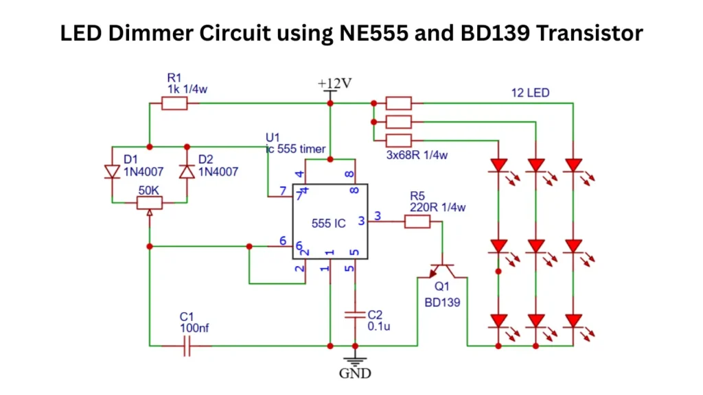
The circuit is designed around the NE555 timer IC, which generates the PWM signal to controlling the brightness of LED. The BD139 transistor acts as a current amplifier, The transistor is allowing the PWM signal to drive multiple LEDs without overloading the 555 timer IC. The brightness of the LEDs is controlled by adjusting the duty cycle of the output signal using a potentiometer.
Working Principle
The NE555 IC is configured in astable mode, where it continuously generates a square wave signal. The frequency and duty cycle of this wave determine the switching rate and brightness of the connected LEDs.
The frequency is primarily set by the resistor, potentiometer, and capacitor network connected to pins 6, 7, and 2 of NE555 IC. The two diodes (D1 and D2) is allow independent control of the charging and discharging paths of the capacitor C1, which enables the duty cycle adjustment without significantly altering the frequency.
The PWM signal is get from the pin 3 (output pin) of the 555 timer has a variable duty cycle. When the duty cycle is high, the LEDs receive more average current and glow brighter. When the duty cycle is low, LED gets less current flows and the LEDs dim.
The output of the 555 timer is not capable of driving high current directly. Therefore, the signal from pin 3 is fed in to the base pin of the BD139 transistor through a 220 Ω resistor (R5).
The BD139 amplifies the current and drives multiple LED strings connected to its collector. This ensures the LEDs operate safely while maintaining brightness control.
The 50 kΩ potentiometer acts as the dimming control. Rotating it changes the charging and discharging times of the timing capacitor (C1), which adjusts the PWM duty cycle. This allows smooth brightness variation from dim to full intensity.
Applications
- LED strip brightness control.
- Automotive dashboard lighting dimmer.
- Decorative or ambient lighting systems.
- Low power lamp dimming projects.