The 555 timer delay circuit is able to delay power on relay from 5 minutes to 20 minutes maximum. This time can be changed by adjusting the 1M potentiometer connected on the 555 timer IC pin number 6 and 7. The complete circuit is powered up using a transformerless power supply. The transformerless power supply includes the 474/ 400v capacitor, 1N4007 full bridge diode and the 12V Zener diode.
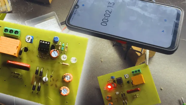
The AC supply is directly connected to the capacitor section and it will be converted to the 12v DC voltage this power is using for the working voltage of the 555 IC circuit and relay.
Rotate the connected 1M potentiometer in clock wise direction to increase the delay power on time. Anti clock wise reduces the power on time.
Circuit Diagram

Components Required
| Component | Quantity |
| 555 timer | 1 |
| 12v relay | 1 |
| BC547 TRANSISTOR | 1 |
| BC557 TRANSISTOR | 1 |
| 100UF CAPACITOR | 1 |
| 1UF CAPACITOR | 1 |
| 1K RESISTOR | 3 |
| 10K RESISTOR | 2 |
| 470K RESISTOR | 1 |
| 10K TO 1M POT | 1 |